P R E L I M I N A R Y
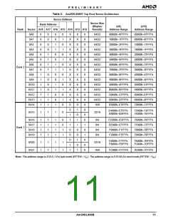
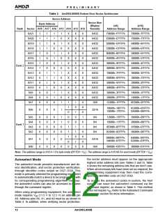
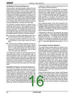
Table 3. Am29DL800BB Bottom Boot Sector Architecture
Sector Address
Sector Size
Bank Address
(Kbytes/
Kwords)
(x8)
(x16)
Address Range
Bank
Sector A18 A17 A16 A15 A14 A13 A12
Address Range
SA21
SA20
SA19
SA18
SA17
SA16
SA15
SA14
SA13
SA12
SA11
SA10
SA9
1
1
1
1
1
1
1
1
0
0
0
0
0
0
0
1
1
1
1
0
0
0
0
1
1
1
1
0
0
0
1
1
0
0
1
1
0
0
1
1
0
0
1
1
0
1
0
1
0
1
0
1
0
1
0
1
0
1
0
1
X
X
X
X
X
X
X
X
X
X
X
X
X
X
1
X
X
X
X
X
X
X
X
X
X
X
X
X
X
1
X
X
X
X
X
X
X
X
X
X
X
X
X
X
X
X
X
1
64/32
64/32
64/32
64/32
64/32
64/32
64/32
64/32
64/32
64/32
64/32
64/32
64/32
64/32
16/8
F0000h–FFFFFh
E0000h–EFFFFh
D0000h–DFFFFh
C0000h–CFFFFh
B0000h–BFFFFh
A0000h–AFFFFh
90000h–9FFFFh
80000h–8FFFFh
70000h–7FFFFh
60000h–6FFFFh
50000h–5FFFFh
40000h–4FFFFh
30000h–3FFFFh
20000h–2FFFFh
1C000h–1FFFFh
78000h–7FFFFh
70000h–77FFFh
68000h–6FFFFh
60000h–67FFFh
58000h–5FFFFh
50000h–57FFFh
48000h–4FFFFh
40000h–47FFFh
38000h–3FFFFh
30000h–37FFFh
28000h–2FFFFh
20000h–27FFFh
18000h–1FFFFh
10000h–17FFFh
0E000h–0FFFFh
Bank 2
SA8
SA7
1
0
18000h–1BFFFh
14000h–17FFFh
0C000h–0DFFFh
0A000h–0BFFFh
SA6
0
0
0
1
32/16
0
1
SA5
SA4
SA3
SA2
0
0
0
0
0
0
0
0
0
0
0
0
1
1
0
0
0
0
8/4
8/4
8/4
8/4
12000h–13FFFh
10000h–11FFFh
0E000h–0FFFFh
0C000h–0DFFFh
09000h–09FFFh
08000h–08FFFh
07000h–07FFFh
06000h–06FFFh
0
0
0
Bank 1
1
1
1
1
1
0
1
0
X
X
X
08000h–0BFFFh,
04000h–07FFFh
04000h–05FFFh,
02000h–03FFFh,
SA1
SA0
0
0
0
0
0
0
0
0
32/16
16/8
0
1
0
0
00000h–03FFFh
00000h–01FFFh
Note: The address range is A18:A-1 if in byte mode (BYTE# = V ). The address range is A18:A0 if in word mode (BYTE# = V ).
IL
IH
the sector address must appear on the appropriate
highest order address bits (see Tables 2 and 3). Table
4 shows the remaining address bits that are don’t care.
When all necessary bits have been set as required, the
programming equipment may then read the corre-
sponding identifier code on DQ7-DQ0.
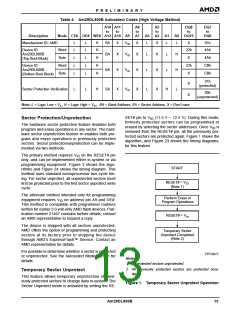
Autoselect Mode
The autoselect mode provides manufacturer and de-
vice identification, and sector protection verification,
through identifier codes output on DQ7–DQ0. This
mode is primarily intended for programming equipment
to automatically match a device to be programmed with
its corresponding programming algorithm. However,
the autoselect codes can also be accessed in-system
through the command register.
To access the autoselect codes in-system, the host
system can issue the autoselect command via the
command register, as shown in Table 5. This method
does not require VID. Refer to the Autoselect Command
Sequence section for more information.
When using programming equipment, the autoselect
mode requires VID (11.5 V to 12.5 V) on address pin
A9. Address pins A6, A1, and A0 must be as shown in
Table 4. In addition, when verifying sector protection,
12
Am29DL800B

 AMD [ AMD ]