Revision J – April 7, 2006
S2004 – Quad Serial Backplane Device
Data Sheet
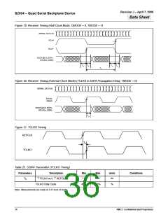
Figure 16. Transmitter Timing (Normal or Channel Lock Mode, TMODE = 0)
REFCLK
DINx[0:7], DNx,
KGENx,
SYNC
T1
T2
SERIAL DATA OUT
Table 19. S2004 Transmitter Timing (Normal or Channel Lock Mode, TMODE = 0)
Parameters
Description
Min
Max
Units
Conditions
T1
0.5
—
ns
See Note 1.
Data Setup w.r.t. ↑ REFCLK
Data Hold w.r.t. ↑ REFCLK
T2
1.5
—
ns
1. All AC measurements are made from the reference voltage levels of the clock (1.4V) to the valid input or output data levels (.8V or 2.0V).
Figure 17. Transmitter Timing (Normal or Channel Lock Mode, TMODE = 1)
TCLKx, TCLKA
DINx[0:7], DNx,
KGENx,
SYNC
T1
T2
SERIAL DATA OUT
Table 20. S2004 Transmitter Timing (Normal or Channel Lock Mode, TMODE = 1)
Parameters
Description
Data Setup w.r.t. ↑ TCLK
Min
Max
Units
Conditions
T1
1.0
—
ns
See Note 1.
T2
0.5
-3
—
ns
ns
Data Hold w.r.t. ↑ TCLK
Phase drift between TCLKx and REFCLK
+3
1. All AC measurements are made from the reference voltage levels of the clock (1.4V) to the valid input or output data levels (.8V or 2.0V).
34
AMCC Confidential and Proprietary

 AMCC [ APPLIED MICRO CIRCUITS CORPORATION ]