Operating Conditions
DC Electrical Characteristics
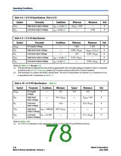
Table 5–4 shows the MAX II device family DC electrical characteristics.
Table 5–4. MAX II Device DC Electrical Characteristics Note (1) (Part 1 of 2)
Symbol
Parameter
Conditions
Minimum
Typical
Maximum
Unit
II
Input pin leakage
current
–10
—
10
µA
VI = VCCIOmax to 0 V (2)
IOZ
Tri-stated I/O pin
leakage current
–10
—
10
µA
VO = VCCIOmax to 0 V (2)
ICCSTANDBY
VCCINT supply
current (standby)
(3)
MAX II devices
MAX IIG devices
EPM240Z
—
—
—
—
—
—
12
2
—
—
mA
mA
µA
29
150
210
—
EPM570Z
32
µA
Hysteresis for
Schmitt trigger
input (5)
V
V
CCIO = 3.3 V
CCIO = 2.5 V
400
190
mV
mV
VSCHMITT (4)
—
ICCPOWERUP
VCCINT supply
current during
power-up (6)
MAX II devices
—
—
55
40
—
—
mA
mA
MAX IIG and MAX IIZ
devices
RPULLUP
Value of I/O pin
pull-up resistor
duringusermode
and in-system
programming
5
—
—
—
—
25
40
60
95
kΩ
kΩ
kΩ
kΩ
VCCIO = 3.3 V (7)
VCCIO = 2.5 V (7)
VCCIO = 1.8 V (7)
VCCIO = 1.5 V (7)
10
25
45
5–4Core Version a.b.c variable
MAX II Device Handbook, Volume 1
Altera Corporation
July 2008

 ALTERA [ ALTERA CORPORATION ]