Dual DMOS Full-Bridge
Microstepping PWM Motor Driver
A3972
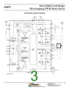
FUNCTIONAL DESCRIPTION
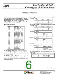
Serial Interface. The A3972SB is controlled via a 3-wire
(clock, data, strobe) serial port. The programmable functions
allow maximum flexibility in configuring the PWM to the motor
drive requirements. The serial data is written as two
19-bit words: 1 bit to select the word and 18 bits of data. The
serial data is clocked in starting with D18.
D13 Bridge 1 Phase. This bit controls the direction of output
current for Load 1.
D13
OUT1A
OUT1B
0
1
L
H
H
L
D14 Bridge 2 Phase. This bit controls the direction of output
current for Load 2.
Word 0 Bit Assignments
Bit
Function
D14
OUT2A
OUT2B
D0
Word select = 0
0
1
L
H
H
L
D1
D2
D3
D4
D5
D6
D7
D8
Bridge 1, DAC, LSB
Bridge 1, DAC, bit 2
Bridge 1, DAC, bit 3
Bridge 1, DAC, bit 4
Bridge 1, DAC, bit 5
Bridge 1, DAC, MSB
Bridge 2, DAC, LSB
Bridge 2, DAC, bit 2
Bridge 2, DAC, bit 3
Bridge 2, DAC, bit 4
Bridge 2, DAC, bit 5
Bridge 2, DAC, MSB
Bridge 1 phase
D15 Bridge 1 Mode.
D15
Mode
0
1
Mixed-decay
Slow-decay
D16 Bridge 2 Mode.
D16
D9
D10
D11
D12
D13
D14
D15
D16
D17
D18
Mode
0
1
Mixed-decay
Slow-decay
Bridge 2 phase
Bridge 1 mode
Bridge 2 mode
REF select
D17 REF Select. This bit determines the reference input for
the 6-bit linear DACs.
D17
Reference Voltage
0
1
Internal 2 V
External (3 V max)
Range select
D1 – D6 Bridge 1 Linear DAC. Six-bit word sets desired
current level for Bridge 1. Setting all six bits to zero disables
Bridge 1, with all drivers off (See current regulation section of
functional description).
D18 Gm Range Select. This bit determines the scaling factor
(4 or 8) used.
D18
Divider
Load Current
0
1
1/8
1/4
ITRIP = VDAC/8RS
ITRIP = VDAC/4RS
D7 – D12 Bridge 2 Linear DAC. Six-bit word sets desired
current level for Bridge 2. Setting all six bits to zero disables
Bridge 2, with all drivers off (See current regulation section of
functional description).
continued next page ...
Allegro MicroSystems, LLC
115 Northeast Cutoff
6
Worcester, Massachusetts 01615-0036 U.S.A.
1.508.853.5000; www.allegromicro.com

 ALLEGRO [ ALLEGRO MICROSYSTEMS ]