3946
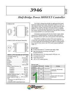
Half-Bridge Power MOSFET Controller
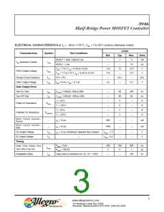
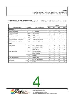
ELECTRICAL CHARACTERISTICS at TA = –40 to +135°C, VBB = 7 to 60 V (unless otherwise noted)
Limits
Characteristics
VBB Quiescent Current
VREG Output Voltage
Symbol
IVBB
Test Conditions
Min.
Typ.
Max.
6
Units
mA
μA
V
RESET = High, Outputs Low
3
–
RESET = Low
10
–
12.0
–
13
VBB > 7.75 V, Ireg = 0 mA to 15 mA
VBB = 7 V to 7.75 V, Ireg = 0 mA to 15 mA
13.5
13.5
VREG
11.0
V
–
Charge Pump Frequency
VREF Output Voltage
Gate Output Drive
Turn On Time
FCP
CP1, CP2
62.5
kHz
V
–
–
VREF
IREF ≤ 4 mA, CREF = 0.1 ꢀF
4.5
5.5
–
trise
tfall
CLOAD = 3300 pF, 20% to 80%
CLOAD = 3300 pF, 80% to 20%
Tj = 25°C
60
40
4
100
80
–
ns
ns
Ω
–
–
–
–
–
–
Turn Off Time
Pullup On Resistance
RDSUP
Tj = 135°C
6
Ω
–
Tj = 25°C
2
Ω
–
Pulldown On Resistance
RDSDOWN
Tj = 135°C
3
Ω
–
Short Circuit Current –
Source
tpw < 10 ꢀs
tpw < 10 ꢀs
800
mA
mA
–
–
–
–
–
–
Short Circuit Current –
Sink
1000
GH Output Voltage
GL Output Voltage
Timing
VGH
VGL
tpw < 10 ꢀs, Bootstrap Capacitor fully charged
VREG – 1.5
VREG – 0.2
V
V
–
–
–
–
–
Rdead = 5 kΩ
200
5
350
6
500
7
ns
Dead Time (Delay from
Turn Off to Turn On)
tDEAD
tPD
Rdead = 100 kΩ
ꢀs
Propagation Delay
Logic input to unloaded GH, GL. DT = VREF
150
ns
–
–
3
www.allegromicro.com
115 Northeast Cutoff, Box 15036
Worcester, Massachusetts 01615-0036 (508) 853-5000

 ALLEGRO [ ALLEGRO MICROSYSTEMS ]