3946
Half-Bridge Power MOSFET Controller
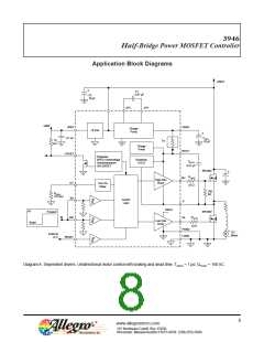
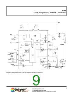
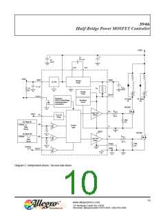
Application Block Diagrams
+VBAT
C1
0.47 μF
C2
10 μF
P
CP2
CP1
VREF
VREF
0.1 uF
VREG
BOOT
Charge
Pump
+5 Vref
CREG
ILIM
10
kΩ
10 μF
L
L
P
P
Charge
Pump
~FAULT
Protection
VREG Undervoltage
Overtemperature
UVLOBOOT
Bootstrap
UVLO
CBOOT
0.47 μF
IRF2807
L
RGATE
GH
High Side
Driver
P
DT
Turn-On
Delay
33 Ω
200
kΩ
RDEAD
15.8 kΩ
IN1
Control
Logic
S
L
VREG
IN
Forward
IRF2807
L
L
RGATE
IN
IN2
GL
Low Side
Driver
Brake
33 Ω
PGND
LGND
DC
Motor
M
External
+5 V
RESET
P
L
L
P
Diagram A. Dependent drivers. Unidirectional motor control with braking and dead time. TDEAD = 1 ꢀs; QTOTAL = 160 nC.
8
www.allegromicro.com
115 Northeast Cutoff, Box 15036
Worcester, Massachusetts 01615-0036 (508) 853-5000

 ALLEGRO [ ALLEGRO MICROSYSTEMS ]