[ASAHI KASEI]
[AK7740ET]
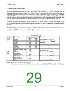
(7) Interface with microcontroller
The microcontroller interface consists of six control signals; RQ (request), SCLK (serial data input clock), SI
(serial data input), SO (serial data output), RDY (ready) and DRDY (data ready). Both write and read operations are
enabled during system reset and run modes. During reset , writing to the control register, program RAM, coefficient
RAM, offset RAM, external conditional jump code, and reading from the program RAM, coefficient RAM and offset
RAM, are enabled. During the run phase, writing of coefficient RAM, offset RAM and external conditional jump
code, and reading of data on the DBUS (data bus) from the SO, are enabled. The data is MSB first serial I/O.
To transfer data to the microcontroller, start by setting RQ “L”, which enables a data read from the DBUS. The
AK7740 reads SI data when SCLK rises, and outputs to SO when SCLK falls. The data format is command followed
by address.
When RQ changes to “H”, then one command is finished. New command requests require setting RQ to “L”
again. When the DBUS data is read, leave RQ =”H” (command code input is not required).
Command Code List
Conditions Code name
for use
Command code
Note:
WRITE
READ
70h
74h
78h
7Ch
C1h
A1h
91h
-
RESET
CONT0
60h
64h
68h
6Ch
C0h
A0h
90h
C4h
82h
A8h
For the function of each bit,
See the description of Control
Registers
phase
CONT1
CONT2
CONT3
PRAM
CRAM
OFRAM
External condition jump
Test
-
Reserved for test
Must occur before CRAM rewrite
RUN
phase
CRAM rewrite
preparation
CRAM rewrite
OFRAM rewrite
preparation
OFRAM rewrite
External condition jump
-
A4h
98h
-
-
Must occur before OFRAM rewite
94h
C4h
-
-
Same command as RESET
NOTE: Do not send any other command codes.
If there is no communication with the microcontroller, set the SCLK to "H” and the SI to "L" for use.
<Pre-E-01>
- 29 -
2006/10

 AKM [ ASAHI KASEI MICROSYSTEMS ]