[AK4679]
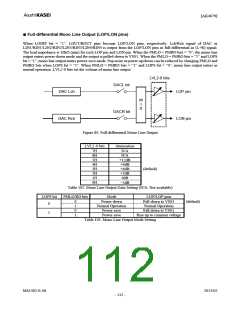
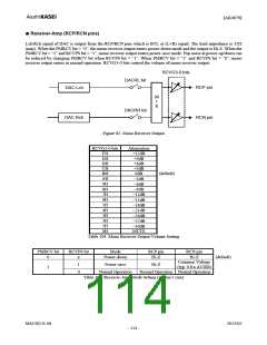
■ Receiver-Amp (RCP/RCN pins)
Lch/Rch signal of DAC is output from the RCP/RCN pins which is BTL as (L+R) signal. The load impedance is 32Ω
(min). When the PMRCV bit = “0”, the mono receiver output enters power-down mode and the output is Hi-Z. When the
PMRCV bit = “1” and RCVPS bit = “1”, mono receiver output enters power-save mode. Pop noise at power-up/down can
be reduced by changing PMRCV bit when RCVPS bit = “1”. When PMRCV bit = “1” and RCVPS bit = “0”, mono
receiver output enters in normal operation. RCVG3-0 bits control the volume of mono receiver output.
RCVG3-0 bits
DACRL bit
RCP pin
RCN pin
DAC Lch
DAC Rch
M
I
X
DACRR bit
Figure 82. Mono Receiver Output
RCVG3-0 bits
Attenuation
+12dB
+9dB
FH
EH
DH
CH
BH
AH
9H
8H
7H
6H
5H
4H
3H
2H
1H
0H
+6dB
+3dB
0dB
−3dB
−6dB
−9dB
−12dB
−15dB
−18dB
−21dB
−24dB
−27dB
−30dB
MUTE
(default)
Table 104. Mono Receiver Output Volume Setting
PMRCV bit
0
RCVPS bit
x
Mode
Power-down
RCP pin
Hi-Z
RCN pin
Hi-Z
(default)
Common Voltage
(typ. 0.8 x AVDD)
Normal Operation Normal Operation
1
0
Power-save
Hi-Z
1
Normal Operation
Table 105. Receiver-Amp Mode Setting (x: Don’t care)
MS1402-E-06
2013/02
- 114 -

 AKM [ ASAHI KASEI MICROSYSTEMS ]