[AK4679]
■ Headphone Output (HPL/HPR pins)
The headphone amplifiers are operated by positive and negative power supplied from charge pump circuit. The VEE pin
outputs the negative voltage generated by the internal charge pump circuit from PVDD. This charge pump circuit is
switched between VDD mode and 1/2VDD mode by the output level of the headphone amplifiers.
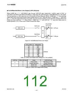
The headphone amplifier output is single-ended and centered on 0V (VSS1). Therefore, the capacitor for AC-coupling
can be removed. The minimum load resistance is 16Ω. The output power is 20mW (@ 0dBFS, RL = 16Ω, AVDD=1.8V,
HPG = -4dB) and 25mW (@ 0dBFS, RL =32Ω, AVDD=1.8V, HPG=0dB).
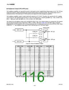
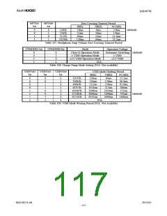
The output level of headphone-amp can be controlled by HPG5-0 bits. This volume setting is in common for L/R channels
and can attenuate/gain the mixer output from +6dB to –62dB in 2dB steps (Table 106). The HPG value is changed
independently on L/R channels by zero crossing or timeout. Zero crossing timeout period is set by HPTM1-0 bits. When
LOHM bit = “1”, the headphone-amp output to HPL and HPR pins as (L+R) mono signal.
HPG5-0 bits
DAC Lch
M
I
X
LOMH bit
LOMH bit
HPL pin
HPR pin
M
I
X
DAC Rch
Figure 84. Stereo Headphone Output
HPG5-0 bits
29H
GAIN (dB)
N/A
N/A
N/A
+6
HPG5-0 bits
14H
GAIN (dB)
−30
−32
−34
28H
27H
26H
13H
12H
11H
−36
25H
+4
10H
−38
24H
23H
22H
21H
20H
1FH
1EH
1DH
1CH
1BH
1AH
19H
+2
0
−2
−4
−6
−8
−10
−12
−14
−16
−18
−20
−22
−24
−26
−28
0FH
0EH
0DH
0CH
0BH
0AH
09H
08H
07H
06H
05H
−40
−42
−44
−46
−48
−50
−52
−54
−56
−58
−60
−62
MUTE
MUTE
MUTE
MUTE
04H
03H
02H
01H
18H
17H
16H
15H
00H
Table 106. Headphone-Amp Volume Setting (Default: 0dB, N/A: Not available)
MS1402-E-06
2013/02
- 116 -

 AKM [ ASAHI KASEI MICROSYSTEMS ]