[AK4679]
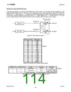
■ Stereo Line Output (LOUT/ROUT pins)
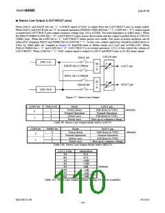
When DACL and DACR bits are “1”, Lch/Rch signal of DAC is output from the LOUT/ROUT pins in single-ended.
When DACL and DACR bits are “0” in normal operation (PMDAC=PML/RO bits = “1”, LOPS bit = “0”), output signal
is muted and LOUT/ROUT pins output common voltage (typ. 0.8 x AVDD). The load impedance is 10kΩ (min.). When
the PMLO=PMRO=LOPS bits = “0”, LOUT/ROUT enters power-down mode and the output is pulled-down to VSS1 by
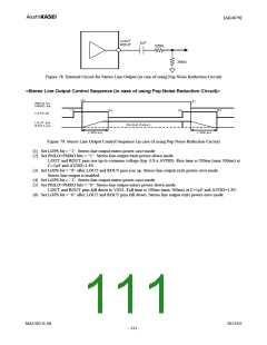
100kΩ (typ). When the LOPS bit is “1”, LOUT/ROUT enters power-save mode. Pop noise at power-up/down can be
reduced by changing PMLO and PMRO bits at LOPS bit = “1”. In this case, output signal line should be pulled-down to
VSS1 by 20kΩ after AC coupled as Figure 78. Rise/Fall time is 300ms (max) at C=1μF and AVDD=1.8V. When
PMLO=PMRO bits = “1” and LOPS bit = “0”, LOUT/ROUT is in normal operation. LVL2-0 bits control the volume of
LOUT/ROUT. When LOM bit = “1”, DAC output signal is output to LOUT and ROUT pins as (L+R) mono signal.
LVL2-0 bits
DACL bit
DAC Lch
M
I
DACR bit x LOM bit
LOUT pin
ROUT pin
X
DACL bit x LOM bit
DACR bit
M
I
X
DAC Rch
Figure 77. Stereo Line Output
Mode LOUT pin
LOPS bit
0
PMLO bit
0
1
0
1
Power-down
Normal Operation
Power-save
Pull-down to VSS1
Normal Operation
Fall down to VSS1
(default)
1
Power-save
Rise up to common voltage
Table 99. Stereo Line Output Mode Select (LOUT)
LOPS bit
0
PMRO bit
Mode
ROUT pin
Pull-down to VSS1
Normal Operation
0
1
0
1
Power-down
Normal Operation
Power-save
(default)
Fall down to VSS1
Rise up to common voltage
1
Power-save
Table 100. Stereo Line Output Mode Select (ROUT)
LVL2-0 bits
Attenuation
N/A
7H
6H
5H
4H
3H
2H
1H
0H
N/A
+6dB
+3dB
0dB
−3dB
−6dB
−9dB
(default)
Table 101. Stereo Line Output Volume Setting (N/A: Not available)
MS1402-E-06
2013/02
- 110 -

 AKM [ ASAHI KASEI MICROSYSTEMS ]