[AK4646]
■ MIC Input Recording (Stereo)
Example:
PLL Master Mode
Audio I/F Format:MSB justified (ADC & DAC)
Pre MIC AMP:+20dB
Sampling Frequency:44.1KHz
MIC Power On
ALC setting:Refer to Figrure 23
ALC1 bit=“1”
FS3-0 bits
(Addr:05H, D5&D2-0)0,000
1,111
(1)
(1) Addr:05H, Data:27H
(2) Addr:02H, Data:05H
MIC Control
001
101
(Addr:02H, D2-0)
(2)
ALC Control 1
00H
3CH
E1H
(3) Addr:06H, Data:3CH
(4) Addr:08H, Data:E1H
(5) Addr:0BH, Data:28H
(6) Addr:07H, Data:21H
(Addr:06H)
(3)
ALC Control 2
E1H
(Addr:08H)
(4)
ALC Control 3
28H
28H
(Addr:0BH)
(5)
ALC Control 4
00H
21H
01H
(7) Addr:00H, Data:41H
Addr:10H, Data:01H
(Addr:07H)
(6)
(9)
ALC State
ALC Disable
ALC Disable
ALC Enable
Recording
PMADL/R bit
(Addr:00H&10H, D0)
(8) Addr:00H, Data:40H
Addr:10H, Data:00H
1059 / fs
(8)
(7)
ADC Internal
State
Power Down
Normal State Power Down
Initialize
(9) Addr:07H, Data:01H
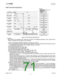
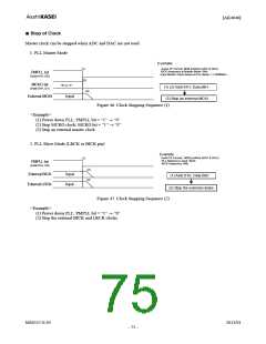
Figure 42. MIC Input Recording Sequence
<Example>
This sequence is an example of ALC setting at fs=44.1kHz. For changing the parameter of ALC, please refer to
“Figure 29. Registers set-up sequence at ALC operation”
At first, clocks should be supplied according to “Clock Set Up” sequence.
(1) Set up a sampling frequency (FS3-0 bit). When the AK4646 is PLL mode, MIC and ADC should be powered-up
in consideration of PLL lock time after a sampling frequency is changed.
(2) Set up MIC input (Addr: 02H)
(3) Set up Timer Select for ALC (Addr: 06H)
(4) Set up IREF value for ALC (Addr: 08H)
(5) Set up LMTH1 and RGAIN1 bits (Addr: 0BH)
(6) Set up LMTH0, RGAIN0, LMAT1-0 and ALC bits (Addr: 07H)
(7) Power Up MIC and ADC: PMADL = PMADR bits = “0” → “1”
The initialization cycle time of ADC is 1059/fs=24ms@fs=44.1kHz.
After the ALC bit is set to “1” and MIC&ADC block is powered-up, the ALC operation starts from IVOL
default value (+30dB).
The time of offset voltage going to “0” after the ADC initialization cycle depends on both the time of analog
input pin going to the common voltage and the constant time of the offset cancel digital HPF. This time can be
shorter by using the following sequence:
At first, PMVCM and PMMP bits should set to “1”. Then, the ADC should be powered-up. The waiting time to
power-up the ADC should be longer than 4 times of the time constant that is determined by the AC coupling
capacitor at analog input pin and the internal input resistance 30k(typ).
(8) Power Down MIC and ADC: PMADL = PMADR bits = “1” → “0”
When the registers for the ALC operation are not changed, ALC bit may be keeping “1”. The ALC operation is
disabled because the MIC&ADC block is powered-down. If the registers for the ALC operation are also changed
when the sampling frequency is changed, it should be done after the AK4646 goes to the manual mode (ALC bit
= “0”) or MIC&ADC block is powered-down (PMADL=PMADR bits = “0”). IVOL gain is not reset when
PMADL=PMADR bits = “0”, and then IVOL operation starts from the setting value when PMADC or PMADR
bit is changed to “1”.
(9) ALC Disable: ALC bit = “1” → “0”
MS0557-E-05
2011/01
- 71 -

 AKM [ ASAHI KASEI MICROSYSTEMS ]