ASAHI KASEI
[AK4387]
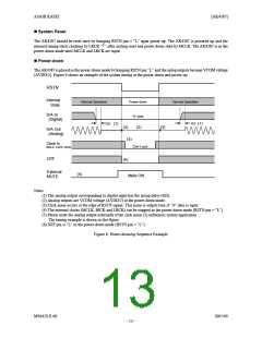
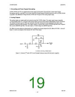
1. Grounding and Power Supply Decoupling
AVDD, DVDD and VSS are supplied from analog supply and should be separated from system digital supply.
Decoupling capacitor, especially 0.1 F ceramic capacitor for high frequency should be placed as near to AVDD, DVDD
µ
as possible. The differential Voltage between AVDD and VSS pins set the analog output range.
2. Analog Outputs
The analog outputs are single-ended and centered around the VCOM voltage. The output signal range is typically
2.95Vpp (typ@AVDD=5V). The phase of the analog outputs can be inverted channel independently by INVL/INVR bits.
The internal switched-capacitor filter and continuous-time filter attenuate the noise generated by the delta-sigma
modulator beyond the audio passband. The output voltage is a positive full scale for 7FFFFFH (@24bit) and a negative
full scale for 800000H (@24bit). The ideal output is VCOM voltage for 000000H (@24bit).
DC offsets on analog outputs are eliminated by AC coupling since analog outputs have DC offsets of VCOM + a few mV.
Figure 11 shows an example of the external LPF with 2Vrms output.
390p
3.3k
3.9k
3.3k
+Vop
22u
3.0k
Analog
Out
AOUT
-Vop
22k
470p
fc=108.6kHz, Q=0.706, g=-0.08dB at 40kHz
Figure 11. External 2nd order LPF Circuit Example (using op-amp with dual power supplies)
MS0429-E-00
2005/09
- 19 -

 AKM [ ASAHI KASEI MICROSYSTEMS ]