ASAHI KASEI
[AK4387]
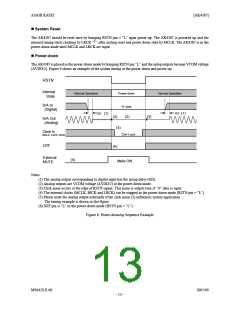
System Reset
The AK4387 should be reset once by bringing RSTN pin = “L” upon power-up. The AK4387 is powered up and the
internal timing starts clocking by LRCK “ ” after exiting reset and power down state by MCLK. The AK4387 is in the
↑
power-down mode until MCLK and LRCK are input.
Power-down
The AK4387 is placed in the power-down mode bybringing RSTN pin “L” and the anlog outputs become VCOM voltage
(AVDD/2). Figure 6 shows an example of the system timing at the power-down and power-up.
RSTN
Internal
State
Normal Operation
Power-down
Normal Operation
D/A In
(Digital)
“0” data
GD
GD
(1)
(1)
(3)
(6)
(2)
(3)
D/A Out
(Analog)
(4)
Clock In
MCLK, LRCK, BICK
Don’t care
DZF
External
MUTE
(5)
Mute ON
Notes:
(1) The analog output corresponding to digital input has the group delay (GD).
(2) Analog outputs are VCOM voltage (AVDD/2) at the power-down mode.
(3) Click noise occurs at the edge of RSTN signal. This noise is output even if “0” data is input.
(4) The external clocks (MCLK, BICK and LRCK) can be stopped in the power-down mode (RSTN pin = “L”).
(5) Please mute the analog output externally if the click noise (3) influences system application.
The timing example is shown in this figure.
(6) DZF pin is “L” in the power-down mode (RSTN pin = “L”).
Figure 6. Power-down/up Sequence Example
MS0429-E-00
2005/09
- 13 -

 AKM [ ASAHI KASEI MICROSYSTEMS ]