[AK4372]
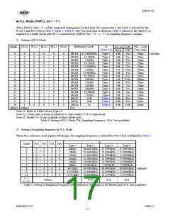
When PLL reference clock input is the LRCK or BICK pin, the sampling frequency is selected by FS3-0 bits. (Table 6)
Mode
FS3 bit
FS2 bit
FS1 bit
FS0 bit
Sampling Frequency Range
0
0
0
0
1
0
1
0
1
0
0
1
2
3
4
1
1
1
1
1
0
0
1
1
0
(default)
32kHz < fs ≤ 48kHz
24kHz < fs ≤ 32kHz
16kHz < fs ≤ 24kHz
12kHz < fs ≤ 16kHz
8kHz ≤ fs ≤ 12kHz
N/A
Others
Others
Table 6. Setting of Sampling Frequency (PLL reference clock input is LRCK or BICK pin) (N/A: Not available)
■ PLL Unlock State
1) PLL Master Mode (PMPLL bit = “1”, M/S bit = “1”)
In master mode (M/S bits = “1”), the LRCK and BICK pins output “L” before the PLL is locked by setting PMPLL =
PMDAC bits = “0” Æ “1”. At that time, the MCKO pin outputs an irregular frequency clock at MCKO bit = “1”. When
MCKO bit = “0”, the MCKO pin outputs “L”. After the PLL is locked, the LRCK and BICK start outputting the clocks
(Table 7).
Master Mode (M/S bit = “1”)
Power Up
Power Down
PLL Unlock
(PMDAC bit= PMPLL bit= “1”) (PMDAC bit= PMPLL bit= “0”)
Input or
MCKI pin Refer to Table 4.
Refer to Table 4.
fixed to “L” or “H” externally
L
MCKO bit = “0”: “L”
MCKO bit = “1”: Output
BF bit = “1”: 64fs output
BF bit = “0”: 32fs output
MCKO bit = “0”: L
MCKO bit = “1”: Unsettling
MCKO pin
BICK pin
L
L
L
L
LRCK pin Output
Table 7. Clock Operation in Master mode (PLL mode)
2) PLL Slave Mode (PMPLL bit = “1”, M/S bit = “0”)
In slave mode (M/S bits = “0”), an invalid clock is output from the MCKO pin when MCKO bit = “1”, before the PLL is
locked by setting PMPLL = PMDAC bits = “0” Æ “1”. When MCKO bit = “0”, the MCKO pin outputs “L”. After the
PLL is locked, the MCKO pin starts outputting the clocks (Table 9).
Slave Mode (M/S bit = “0”)
Power Up
Power Down
PLL Unlock
(PMDAC bit= PMPLL bit= “1”) (PMDAC bit= PMPLL bit= “0”)
Input or
MCKI pin Refer to Table 4.
Refer to Table 4.
fixed to “L” or “H” externally
L
MCKO bit = “0”: “L”
MCKO bit = “1”: Output
MCKO bit = “0”: L
MCKO bit = “1”: Unsettling
Input or
MCKO pin
BICK pin
Input
Input
Fixed to “L” or “H” externally Fixed to “L” or “H”
externally
Input or
Fixed to “L” or “H” externally Fixed to “L” or “H”
externally
LRCK pin
Table 8. Clock Operation in Slave mode (PLL mode)
MS0684-E-02
2008/12
- 18 -

 AKM [ ASAHI KASEI MICROSYSTEMS ]