ASAHI KASEI
[AK4115]
System Reset and Power-Down
The AK4115 has a power-down mode for all circuits by PDN pin and can be partially powerd-down by PWN bit. The
RSTN bit initializes the register and resets the internal timing. In parallel mode, only the control by PDN pin is enabled.
The AK4115 should be reset once by bringing PDN pin = “L” upon power-up.
PDN Pin:
All analog and digital circuits are placed in power-down and reset mode by bringing PDN pin= “L”. All the
registers are initialized, and clocks are stopped. Reading/Writing to the registers is disabled.
RSTN Bit (Address 00H; D0):
All the registers except PWN and RSTN bits are initialized by bringing RSTN bit = “0”. The internal timing is
also initialized. Writing to registers is not available except the PWN and RSTN bits. Reading from the
registers is disabled.
PWN Bit (Address 00H; D1):
The clock recovery is initialized by bringing PWN bit = “0”. In this case, the clocks are stopped. The registers
are not initialized and the mode settings are maintained. Writing and reading to the registers are enabled.
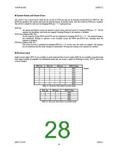
Bi-phase Input
Eight receiver inputs (RX7-0) are available in serial mode and four receiver inputs (RX3-0) are available in parallel mode.
Each input includes an amplifier for unbalanced mode that can accept a signal of 200mVpp or more. IPS2-0 selects the
receiver channel.
IPS2 bit
IPS1 bit
IPS0 bit
INPUT Data
RX0
0
0
0
0
1
1
1
1
0
0
1
1
0
0
1
1
0
1
0
1
0
1
0
1
Default
RX1
RX2
RX3
RX4
RX5
RX6
RX7
Table 19. Recovery Data Select in serial mode
IPS1 pin
IPS0 pin
INPUT Data
RX0
0
0
1
1
0
1
0
1
RX1
RX2
RX3
Table 20. Recovery Data Select in parallel mode
MS0573-E-00
2006/12
- 28 -

 AKM [ ASAHI KASEI MICROSYSTEMS ]