ASAHI KASEI
[AKD4113-B]
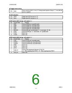
Toggle switch set-up
Reset switch for AK4113. Set to “H” during normal operation. Bring to “L” once after the
power is supplied.
SW2
PDN
LED indication
LE1
LE2
Bright when INT0 pin goes to “H”.
Bright when INT1 pin goes to “H”.
INT0
INT1
DIP switch (SW1) set-up: -off- means “L”
No.
1
2
3
4
5
6
7
Switch Name
IPS0
DIF0
DIF1
DIF2
IPS1/IIC
P/SN
TEST
Function
Set-up of IPS0 pin. (in parallel mode)
Set-up of DIF0 pin. (in parallel mode)
Set-up of DIF1 pin. (in parallel mode)
Set-up of DIF2 pin. (in parallel mode)
Set-up of IIC pin. (in serial mode) “L”: 4 wire Serial, “H”: IIC
Set-up of P/SN pin. “L”: Serial mode, “H”: parallel mode
Don’t care
8
ACKS
Don’t care
DIP switch (SW3) set-up: -off- means “L”
No.
1
Switch Name
CM1
Function
Set-up of CM1 pin. (in parallel mode)
2
3
4
OCKS1
OCKS0
PSEL
Set-up of OCKS1 pin. (in parallel mode)
Set-up of OCKS0 pin. (in parallel mode)
Don’t care
5
XTL0
Don’t care
6
XTL1
Don’t care
Set-up of the transmission direction of 74AC245
“L”: When inputting from PORT2, “H”: When outputting from PORT2
Don’t care
DIR_I/O
DIT_I/O
7
8
<KM076501>
2004/11
- 6 -

 AKM [ ASAHI KASEI MICROSYSTEMS ]