Ambassador T8100A, T8102, and T8105
H.100/H.110 Interfaces and Time-Slot Interchangers
Advance Data Sheet
November 1999
5 Outline Diagrams (continued)
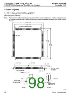
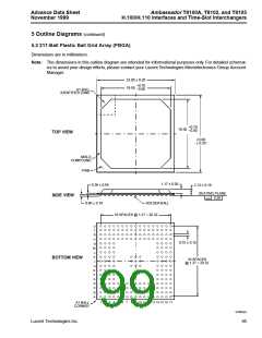
5.2 217-Ball Plastic Ball Grid Array (PBGA)
Dimensions are in millimeters.
Note: The dimensions in this outline diagram are intended for informational purposes only. For detailed schemat-
ics to assist your design efforts, please contact your Lucent Technologies Microelectronics Group Account
Manager.
23.00 ± 0.20
+0.70
19.50
–0.00
A1 BALL
IDENTIFIER ZONE
+0.70
–0.00
19.50
TOP VIEW
23.00
± 0.20
MOLD
COMPOUND
PWB
1.17 ± 0.05
0.36 ± 0.04
2.13 ± 0.19
SEATING PLANE
0.20
SIDE VIEW
0.60 ± 0.10
SOLDER BALL
16 SPACES @ 1.27 = 20.32
U
T
R
P
N
M
0.75 ± 0.15
L
K
J
BOTTOM VIEW
16 SPACES
@ 1.27 = 20.32
H
G
F
E
D
C
B
A
1
2
3
4
5
6
7
8 9 10 11 12 13 14 15 16 17
A1 BALL
CORNER
5-6562(F)
Lucent Technologies Inc.
95

 AGERE [ AGERE SYSTEMS ]