Ambassador T8100A, T8102, and T8105
H.100/H.110 Interfaces and Time-Slot Interchangers
Advance Data Sheet
November 1999
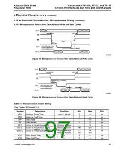
4 Electrical Characteristics (continued)
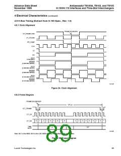
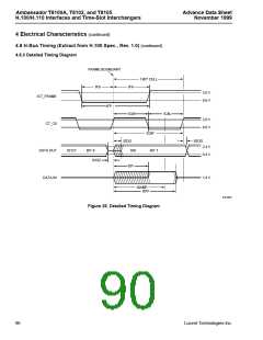
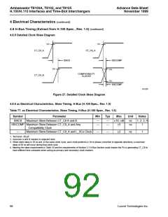
4.8 H-Bus Timing (Extract from H.100 Spec., Rev. 1.0) (continued)
4.8.7 Reset and Power On
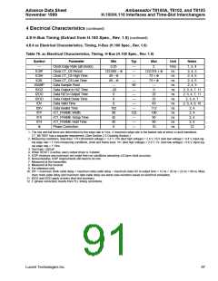
Table 78. Reset and Power On
Symbol
Parameter
Min
Typ
Max
Unit
tRD
tRS
Output Float Delay from Reset Active
Reset Active from Power Good
—
—
—
5
1
µs
µs
—
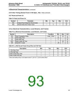
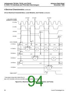
4.9 ac Electrical Characteristics, Local Streams, and Frames
Table 79. ac Electrical Characteristics, Local Streams, and Frames
Symbol
Description
Data Propagation Delay
Condition
Min
Max
Unit
tPD
tS
Load = 50 pF
0
10
5
20
—
—
20
0
ns
ns
ns
ns
ns
Data Setup Time
Data Hold Time
—
—
—
—
tH
tOFF
tD0
Data 3-state Off Time
Data Bit 0 3-state
—
–20
Table 80. L_SC[3:0] and Frame Group Rise and Fall Time
Description Min
Typ
Max
Unit*
L_SCx Rise Time
L_SCx Fall Time
—
—
—
—
—
—
—
—
5
4
3
3
ns
ns
ns
ns
Frame Group Rise Time
Frame Group Fall Time
* Worst-case loading of 50 pF on all outputs except CT_D[31:0]. CT_D[31:0] drives 200 pF.
Lucent Technologies Inc.
89

 AGERE [ AGERE SYSTEMS ]