Ambassador T8100A, T8102, and T8105
H.100/H.110 Interfaces and Time-Slot Interchangers
Advance Data Sheet
November 1999
2 Architecture and Functional Description (continued)
2.5 Clocking Section (continued)
2.5.8 Clock Control Register Definitions (continued)
2.5.8.1 Basic Fallback Mode (continued)
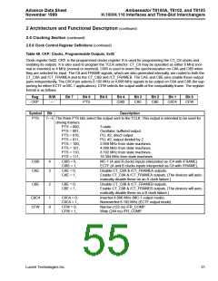
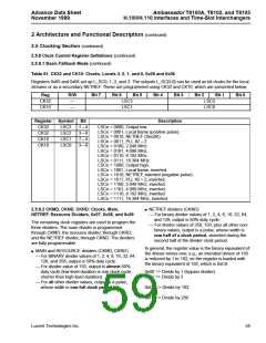
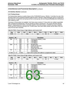
Table 51. CK32 and CK10: Clocks, Locals 3, 2, 1, and 0, 0x05 and 0x06
Registers 0x05 and 0x06 set up L_SC0, 1, 2, and 3. The outputs L_SC[3:0] can be used as bit clocks for the local
streams or as a secondary NETREF. These are programmed using CK32 and CK10, which are presented below.
Reg
CK32
CK10
R/W
—
Bit 7
Bit 6
Bit 5
Bit 4
Bit 3
Bit 2
Bit 1
Bit 0
LSC3
LSC1
LSC2
LSC0
—
Register Symbol
Bit
Description
CK32
CK32
CK10
CK10
LSC3
LSC2
LSC1
LSC0
7—4
3—0
7—4
3—0
LSCn = 0000, Output low.
LSCn = 0001, Local frame (positive pulse).
LSCn = 0010, NETREF (Sec8K).
LSCn = 0011, PLL #2 ÷ 2.
LSCn = 0100, 2.048 MHz.
LSCn = 0101, 4.096 MHz.
LSCn = 0110, 8.192 MHz.
LSCn = 0111, 16.384 MHz.
LSCn = 1000, Output high.
LSCn = 1001, Local frame, inverted.
LSCn = 1010, NETREF, inverted (negative pulse).
LSCn = 1011, PLL #2 ÷ 2, inverted.
LSCn = 1100, 2.048 MHz, inverted.
LSCn = 1101, 4.096 MHz, inverted.
LSCn = 1110, 8.192 MHz, inverted.
LSCn = 1111, 16.384 MHz, inverted.
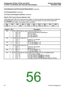
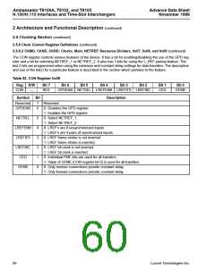
2.5.8.2 CKMD, CKND, CKRD: Clocks, Main,
■ NETREF dividers (CKND)
NETREF, Resource Dividers, 0x07, 0x08, and 0x09
— For binary divider values of 1, 2, 4, 8, 16, 32, 64,
and 128, output is 50% duty cycle.
— For divider values of 256, 193, plus all other non-
binary values, output is a pulse, whose width is
one half of a clock period, asserted during the
second half of the divider clock period.
The remaining clock registers are used to program the
three dividers. The main divider is programmed
through CKMD; the resource divider, through CKRD;
and the NETREF divider, through CKND. The dividers
are fully programmable.
In general, the register value is the binary equivalent of
the divisor-minus-one; e.g., an intended divisor of 193
is reduced by 1 to 192, so the register is loaded with
the binary equivalent of 192, which is 0xC0.
■ MAIN and RESOURCE dividers (CKMD, CKRD)
— For BINARY divider values of 1, 2, 4, 8, 16, 32, 64,
128, and 256, output is 50% duty cycle.
— For divider value of 193, output is almost 50%
duty cycle (low-level duration is one clock cycle
shorter than high-level duration).
0x00 => Divide by 1 (bypass divider)
0x01 => Divide by 2
— For all other divider values, output is a pulse,
whose width is one full clock period.
:
0xC0 => Divide by 193
:
0xFF => Divide by 256
Lucent Technologies Inc.
55

 AGERE [ AGERE SYSTEMS ]