Ambassador T8100A, T8102, and T8105
H.100/H.110 Interfaces and Time-Slot Interchangers
Advance Data Sheet
November 1999
2 Architecture and Functional Description (continued)
2.3 H-Bus Section (continued)
2.3.1 Memory Architecture (continued)
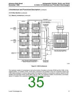
READ/WRITE
VALID ENTRY MARKER
ADDRESS
TAG
PATTERN/NORMAL
DATA SRAM SELECT
A
11
A
1
T
7
T
0
…………………
………………
0
PATTERN MODE
OUTPUTS TAG
TO H-BUS
READ/WRITE AND
SRAM SELECT
H-BUS:
EVEN STREAMS
A12 = 0
CAM-E
CE-SRAM
A0 = 0
255
ADDRESS
TAG
D
7
D D
0
D
0
………………
………………
7
A
11
A
1
T
7
T
0
0
…………………
………………
0
H-BUS:
ODD STREAMS
1 = 01
H-BUS
CAM-O
CO-SRAM
DATA SRAM
A12 = 0
A0 = 1
255
0
ADDRESS
TAG
255
A
10
A
0
T
7
T
0
DATA BUFFER 0 DATA BUFFER 1
…………………
………………
THIS IS THE H-BUS DATA MEMORY:
EFFECTIVE ACCESS TIME < 10 ns
LOCAL 0—15
A12:A11 = 11
CAM-L
CL-SRAM
LOCAL I/O
255
THIS IS THE H-BUS CONNECTION MEMORY:
3 CAMS, MAXIMUM OF 48 ACCESSES PER 976 ns
TIME SLOT, REQUIRES <20 ns/ACCESS
PATTERN MODE
OUTPUTS TAG
TO LOCAL OUT
5-6108F
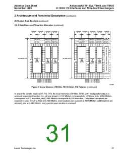
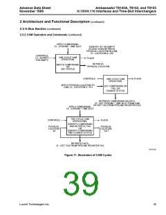
Figure 9. CAM Architecture
The maximum number of connections is set by the number of locations in the data SRAM and the CAMs. In this
implementation, 512 simplex (T8102, T8105 only) connections are permitted. Since one connection requires two
CAM entries pointing to a common data location, the maximum number of connections could be reduced to 256
simplex if all connection entries reside within only one CAM. The maximum number of connections is increased
above 512 simplex if the connection type is broadcast, i.e., from one to many.
Lucent Technologies Inc.
31

 AGERE [ AGERE SYSTEMS ]