Ambassador T8100A, T8102, and T8105
H.100/H.110 Interfaces and Time-Slot Interchangers
Advance Data Sheet
November 1999
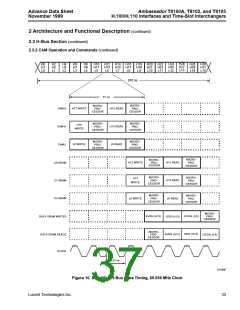
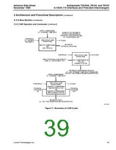
The CAM commands make use of either one or two
cycles. The two cycles are described pictorially in Fig-
ure 11. The reader will note that matching and retrieval
are actually separate cycles. The need for two cycles
accounts for the requirement of the pipeline register
files.
2 Architecture and Functional
Description (continued)
2.3 H-Bus Section (continued)
2.3.2 CAM Operation and Commands (continued)
Detailed descriptions of the commands follow:
A number of commands are available to control the
CAMs. Connections can be made or broken, entry data
can be searched for, individual locations may be read
or cleared, or the CAMs can be reset. The address
mode register (AMR) (see Section 2.1 Register/Mem-
ory Maps) is used to issue the CAM control commands.
Some commands require the use of the lower address
register (LAR), and some use the IDR as a transfer reg-
ister.
The basic make connection command is referred to as
MKCn, where n is the CAM designator*. The MKCn
uses two CAM cycles: first, the CAM is searched to
determine where to find the next free location (as deter-
mined by the validity bits), and during the second cycle,
the next empty location is written into. The MKCn com-
mand uses holding registers which convey the connec-
tion information to the CAM and its associated register
file. The four holding registers contain the lower con-
nection address (i.e., time slot), the upper connection
address (stream plus control bits), the tag LSBs, the
subrate control (7 bits), and the tag MSB. An attempt to
write to a full CAM (all 512 locations fully occupied in
the T8102 and T8105) results in an overflow error
flagged through the system error register, SYSERR
(see Section 2.7 Error Registers).
The tags in each CAM’s associated register file refer-
ence the storage location of the data being transferred,
so each CAM/tag location also has control information.
The three control bits are read-to/write-from data
SRAM (i.e., a direction bit, located in the CAM and
used during the comparison operations), a pattern
mode enable, which bypasses the data SRAM and out-
puts the tag directly into the specified time slot for
writes to the bus, and an SRAM buffer select that con-
trols the minimum delay or constant delay select,
equivalent to the local memory’s (T8100A, T8105 only)
selection of minimum or constant delay.
Note: A single MKCn command only specifies one-
half of a connection. The MKCn specifies the
connection address and a pointer to the data
memory, but a second connection address and
pointer to the same data memory location must
also be provided for a complete connection.
In addition, the CAM carries a valid entry bit. This is an
identifier for the status of the CAM (and corresponding
register file) location. If the bit is low, as all validity bits
are after a reset, then the location is available to be
written into. When data is written into a location, then
this bit is set, indicating that this is a valid entry. If spe-
cific data is no longer valid, such as when a connection
is broken, then the bit is cleared.
* The H-bus CAM covering the 16 even-numbered H-bus streams is
designated E, the H-bus CAM covering the 16 odd-numbered H-bus
streams is designated O, and the CAM that services the 16 local
stream pairs is designated L.
34
Lucent Technologies Inc.

 AGERE [ AGERE SYSTEMS ]