Ambassador T8100A, T8102, and T8105
H.100/H.110 Interfaces and Time-Slot Interchangers
Advance Data Sheet
November 1999
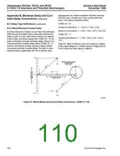
Appendix A. Application of Clock Modes (continued)
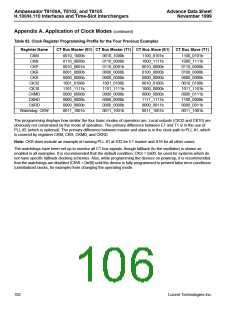
Table 82. Clock Register Programming Profile for the Four Previous Examples
Register Name
CT Bus Master (E1) CT Bus Master (T1) CT Bus Slave (E1)
CT Bus Slave (T1)
CKM
CKN
0010_1000b
0110_0000b
0010_0001b
0001_0000b
0000_0000b
1001_0100b
1101_1111b
0000_0000b
0000_0000b
0000_0000b
0011_1001b
0010_1000b
0110_0000b
0110_0001b
0000_0000b
0000_0000b
1001_0100b
1101_1111b
0000_0000b
0000_0000b
0000_0000b
0011_1001b
1100_0101b
1000_1111b
0010_0000b
0100_0000b
0000_0000b
0010_0100b
1000_0000b
0000_0000b
1111_1111b
0000_0011b
0011_1001b
1100_0101b
1000_1111b
0110_0000b
0100_0000b
0000_0000b
0010_0100b
1011_1101b
0000_0111b
1100_0000b
0000_0011b
0011_1001b
CKP
CKR
CKS
CK32
CK10
CKMD
CKND
CKRD
Watchdog: CKW
The programming displays how similar the four basic modes of operation are. Local outputs (CK32 and CK10) are
obviously not constrained by the mode of operation. The primary difference between E1 and T1 is in the use of
PLL #2 (which is optional). The primary difference between master and slave is in the clock path to PLL #1, which
is covered by registers CKM, CKR, CKMD, and CKRD.
Note: CKR does include an example of running PLL #1 at X32 for E1 master and X16 for all other cases.
The watchdogs have been set up to monitor all CT bus signals, though fallback (to the oscillator) is shown as
enabled in all examples. It is recommended that the default condition, CKS = 0x00, be used for systems which do
not have specific fallback clocking schemes. Also, while programming the devices on powerup, it is recommended
that the watchdogs are disabled (CKW = 0x00) until the device is fully programmed to prevent false error conditions
(uninitialized clocks, for example) from changing the operating mode.
102
Lucent Technologies Inc.

 AGERE [ AGERE SYSTEMS ]