Ambassador T8100A, T8102, and T8105
H.100/H.110 Interfaces and Time-Slot Interchangers
Advance Data Sheet
November 1999
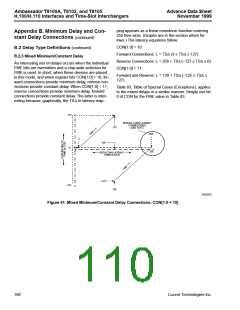
ping appears as a linear monotonic function covering
255 time slots. (Graphs are in the section which fol-
lows.) The latency equations follow:
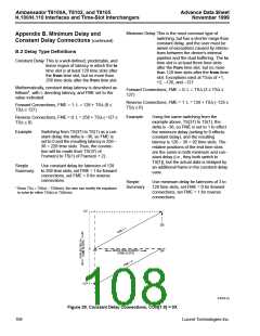
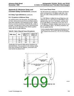
Appendix B. Minimum Delay and Con-
stant Delay Connections (continued)
CON[1:0] = 10:
B.2 Delay Type Definitions (continued)
Forward Connections: L = TS∆ (3 ≤ TS∆ ≤ 127).
Reverse Connections: L = 256 + TS∆ (–127 ≤ TS∆ ≤ 0).
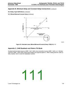
CON[1:0] = 11:
B.2.3 Mixed Minimum/Constant Delay
An interesting mix of delays occurs when the individual
FME bits are overridden and a chip-wide selection for
FME is used. In short, when these devices are placed
in this mode, and when register bits CON[1:0] = 10, for-
ward connections provide minimum delay, reverse con-
nections provide constant delay. When CON[1:0] = 11,
reverse connections provide minimum delay, forward
connections provide constant delay. The latter is inter-
esting because, graphically, the TS∆ to latency map-
Forward and Reverse: L = 128 + TS∆ (–125 ≤ TS∆ ≤
127).
Table 83, Table of Special Cases (Exceptions), applies
to the mixed delays in a similar manner. Simply use bit
0 of CON for the FME value in Table 83.
127
SPECIAL LONG LATENCY
CONNECTIONS
127
(SEE TEXT)
258
2
128
2
0
0
256
RESULTING LATENCY
(TIME SLOTS)
–127
–127
129
5-6225(F)
Figure 41. Mixed Minimum/Constant Delay Connections, CON[1:0 = 10]
106
Lucent Technologies Inc.

 AGERE [ AGERE SYSTEMS ]