Data Sheet
July 2000
LU6612
FASTCAT Single-FET for 10Base-T/100Base-TX
Pin Information (continued)
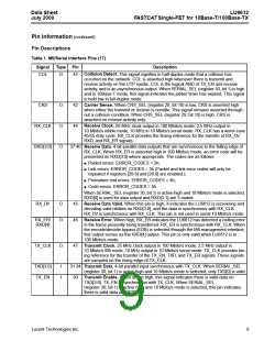
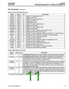
Table 4. Ground and Power Pins (21)
Signal
VCCIOA
GNDIOA
VCCIOB
GNDIOB
GNDIOC
VCCDIGA
GNDDIGA
VCCDIGB
GNDDIGB
VCCREC
GNDREC
VCCPLL
GNDPLL
VCCT
Type
PWR
PWR
PWR
PWR
PWR
PWR
PWR
PWR
PWR
PWR
PWR
PWR
PWR
PWR
PWR
PWR
PWR
PWR
PWR
PWR
PWR
Pin
6
Description
Digital +5 V power supply for I/O
7
Digital ground for I/O
54
53
41
35
36
49
48
60
59
20
23
11
10
61
64
1
Digital +5 V power supply for I/O
Digital ground for I/O
Digital ground for I/O
Digital +5 V power supply for logic
Digital ground for logic
Digital +5 V power supply for logic
Digital ground for logic
Digital +5 V power supply for clock recovery circuit
Digital ground for clock recovery circuit
Analog +5 V power supply for 10 MHz and 100 MHz PLL clock synthesizer
Analog ground for 10 MHz and 100 MHz PLL clock synthesizer
Analog +5 V power supply for transmitter
Analog ground for transmitter
GNDT
VCCEQAP
GNDEQAP
VCCBG
Analog +5 V power supply for equalizer and adaptation circuit
Analog ground for adaptation circuit.
Analog +5 V power supply for band-gap circuit
Analog ground band-gap circuit
GNDBG
VCCBT
3
14
13
Analog +5 V power supply for 10Base-T transmitter
Analog ground for 10Base-T transmitter
GNDBT
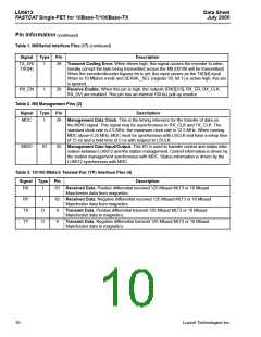
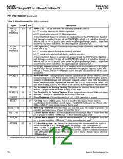
Table 5. Miscellaneous Pins (20)
Signal
Type* Pin
Description
LSCLK1
I
21 Local Symbol Clock. 25 MHz clock, ±100 ppm, 40%—60% duty cycle. This input is
connected to one terminal of a 25 MHz crystal or an external 25 MHz clock source.
LSCLK2
O
22 Local Symbol Clock. 25 MHz crystal feedback. This output is connected to the
other terminal of a 25 MHz crystal or an external 25 MHz. If LSCLK1 is driven from
an external clock source, LSCLK2 is left unconnected.
LINKLED/
PHYAD[0]
I/O
I/O
4
Link LED. This pin indicates good link status. At powerup/reset, this pin is sampled
as input and to set the PHYAD[0] bit. If pulled high through a resistor, this pin will set
PHYAD[0] to a high or if pulled low through a resistor, will set PHYAD[0] to a zero.
When this pin is pulled high the LED output will be active-low, when pulled low the
LED output will be active-high.
ACTLED/
PHYAD[1]
5
Activity LED. This pin indicates transmit/receive activity. At powerup/reset, this pin
is sampled as input to set the PHYAD[1] bit. If pulled high through a resistor, this pin
will set PHYAD[1] to a high or if pulled low through a resistor, will set PHYAD[1] to a
zero. When this pin is pulled high the LED output will be active-low, when pulled low
the LED output will be active-high.
* ↑ indicates there is an internal pull-up; ↓ indicates there is an internal pull-down.
Lucent Technologies Inc.
11

 AGERE [ AGERE SYSTEMS ]