LU6612
Data Sheet
July 2000
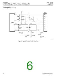
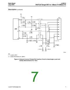
FASTCAT Single-FET for 10Base-T/100Base-TX
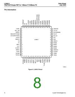
Pin Information (continued)
Table 1. MII/Serial Interface Pins (17) (continued)
Signal
Type Pin
Description
TX_ER/
TXD[4]
I
29 Transmit Coding Error. When driven high, this signal causes the encoder to inten-
tionally corrupt the byte being transmitted across the MII (00100 will be transmitted).
When the encoder/decoder bypass bit is set, this input serves as the TXD[4] input.
When in 10 Mbits/s mode and SERIAL_SEL (register 30, bit 1) is active-high, this pin
is ignored.
RX_EN
I
28 Receive Enable. When this pin is high, the outputs (RXD[3:0], RX_ER, RX_CLK,
RX_DV) are enabled. This pin has an internal 100 kΩ pull-up resistor.
Table 2. MII Management Pins (2)
Signal
Type Pin
Description
MDC
I
26 Management Data Clock. This is the timing reference for the transfer of data on
the MDIO signal. This signal may be asynchronous to RX_CLK and TX_CLK. The
standard clock rate is 2.5 MHz, the maximum clock rate is 12.5 MHz. When running
MDC above 6.25 MHz, MDC must be synchronous with LSCLK and have a setup time
of 15 ns and a hold time of 5 ns with respect to LSCLK.
MDIO
IO
25 Management Data Input/Output. This I/O is used to transfer control and status infor-
mation between LU6612 and the station management. Control information is driven by
the station management synchronous with MDC. Status information is driven by the
LU6612 synchronous with MDC.
Table 3. 10/100 Mbits/s Twisted-Pair (TP) Interface Pins (4)
Signal Type Pin
Description
RX
RY
TX
TY
I
63 Received Data. Positive differential received 125 Mbaud MLT3 or 10 Mbaud
Manchester data from magnetics.
I
62 Received Data. Negative differential received 125 Mbaud MLT3 or 10 Mbaud
Manchester data from magnetics.
O
O
8
9
Transmit Data. Positive differential transmit 125 Mbaud MLT3 or 10 Mbaud
Manchester data to magnetics.
Transmit Data. Negative differential transmit 125 Mbaud MLT3 or 10 Mbaud
Manchester data to magnetics.
10
Lucent Technologies Inc.

 AGERE [ AGERE SYSTEMS ]