ADSP-BF542/ADSP-BF544/ADSP-BF547/ADSP-BF548/ADSP-BF549
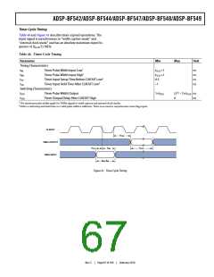
Table 43. Serial Ports—Enable and Three-State
Parameter
Min
0
Max
Unit
Switching Characteristics
tDTENE
tDDTTE
tDTENI
tDDTTI
Data Enable Delay from External TSCLKx1
ns
ns
ns
ns
Data Disable Delay from External TSCLKx1, 2
Data Enable Delay from Internal TSCLKx1
Data Disable Delay from Internal TSCLKx1, 2
10.0
3.0
–2.0
1 Referenced to drive edge.
2 Applicable to multichannel mode only.
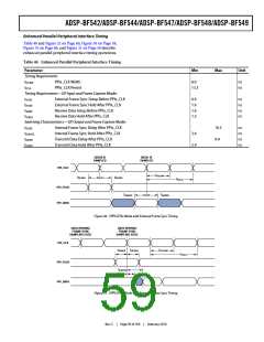
DRIVE EDGE
DRIVE EDGE
TSCLKx
DTx
tDTENE/I
tDDTTE/I
Figure 36. Serial Ports—Enable and Three-State
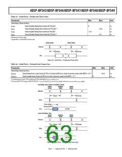
Table 44. Serial Ports—External Late Frame Sync
Parameter
Min
Max
10.0
Unit
Switching Characteristics
tDDTLFSE
Data Delay from Late External TFSx or External RFSx in multi-channel mode with MFD = 011, 2
Data Enable from External RFSx in multi-channel mode with MFD = 01, 2
ns
ns
tDTENLFSE
0
1 In multichannel mode, TFSx enable and TFSx valid follow tDTENLFS and tDDTLFSE
.
2 If external RFS/TFS setup to RSCLK/TSCLK > tSCLKE/2, then tDDTE/I and tDTENE/I apply; otherwise tDDTLFSE and tDTENLFS apply.
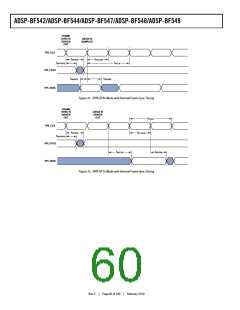
EXTERNAL RFSx IN MULTI-CHANNEL MODE
DRIVE
EDGE
SAMPLE
EDGE
DRIVE
EDGE
RSCLKx
RFSx
tSFSE/I
tHOFSE/I
tDDTLFSE
tDTENLFSE
DTx
1ST BIT
LATE EXTERNAL TFSx
DRIVE
EDGE
SAMPLE
EDGE
DRIVE
EDGE
TSCLKx
tSFSE/I
tHOFSE/I
TFSx
tDDTLFSE
DTx
1ST BIT
Figure 37. Serial Ports—External Late Frame Sync
Rev. C
|
Page 63 of 100
|
February 2010

 ADI [ ADI ]