Data Sheet
ADM3055E/ADM3057E
ADM3057E
See Table 11 and the Insulation Lifetime section for details regarding maximum working voltages for specific cross isolation waveforms
and insulation levels. The ADM3057E is approved or pending approval by the organizations listed in Table 6.
Table 6.
UL (Pending)1
CSA (Pending)
VDE (Pending)2
CQC (Pending)
Recognized under 1577
Component Recognition
Program1
Approved under CSA Component
Acceptance Notice 5A
DIN V VDE V 0884-10
(VDE V 0884-10):2006-12
Certified under
CQC11-471543-2012
Single Protection, 3000 V rms CSA 60950-1-07+A1+A2 and
Reinforced insulation 849 VPEAK
surge isolation voltage (VIOTM) =
6000 VPEAK
,
GB4943.1-2011: basic
insulation at 780 V rms
Isolation Voltage
IEC 60950-1, second edition, +A1+A2
Basic insulation at 780 V rms (1103 VPEAK
Reinforced insulation at 390 V rms
(1103 VPEAK
Reinforced insulation at
390 V rms (552 VPEAK
)
)
)
(552 VPEAK
)
IEC 60601-1 Edition 3.1:
Basic insulation (1 MOPP), 490 V rms
(693 VPEAK
Reinforced insulation (2 MOPP),
250 V rms (353 VPEAK
)
)
CSA 61010-1-12 and IEC 61010-1 third
edition
Basic insulation at 300 V rms mains,
780 V secondary (1103 VPEAK
)
Reinforced insulation at 300 V rms
mains, 390 V secondary (552 VPEAK
File 205078
)
File E214100
File 2471900-4880-0001
File (pending)
1 In accordance with UL 1577, each ADM3057E is proof tested by applying an insulation test voltage ≥ 3600 V rms for 1 sec.
2 In accordance with DIN V VDE V 0884-10, each ADM3057E is proof tested by applying an insulation test voltage ≥ 1592 VPEAK for 1 sec (partial discharge detection limit =
5 pC). The * marking branded on the component designates DIN V VDE V 0884-10 approval.
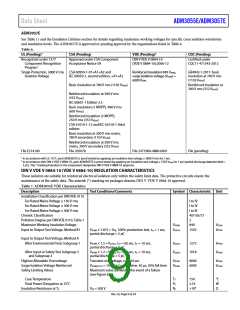
DIN V VDE V 0884-10 (VDE V 0884-10) INSULATION CHARACTERISTICS
These isolators are suitable for reinforced electrical isolation only within the safety limit data. The protective circuits ensure the
maintenance of the safety data. The asterisk (*) marking on packages denotes DIN V VDE V 0884-10 approval.
Table 7. ADM3055E VDE Characteristics
Description
Test Conditions/Comments
Symbol Characteristic Unit
Installation Classification per DIN VDE 0110
For Rated Mains Voltage ≤ 150 V rms
For Rated Mains Voltage ≤ 300 V rms
For Rated Mains Voltage ≤ 400 V rms
Climatic Classification
Pollution Degree per DIN VDE 0110, Table 1
Maximum Working Insulation Voltage
Input to Output Test Voltage, Method B1
I to IV
I to IV
I to III
40/105/21
2
VIORM
Vpd(m)
849
1592
VPEAK
VPEAK
VIORM × 1.875 = VPR, 100% production test, tm = 1 sec,
partial discharge < 5 pC
Input to Output Test Voltage, Method A
After Environmental Tests Subgroup 1
VIORM × 1.5 = Vpd(m), tini = 60 sec, tm = 10 sec,
partial discharge < 5 pC
VIORM × 1.2 = Vpd(m), tini = 60 sec, tm = 10 sec,
partial discharge < 5 pC
Vpd(m)
Vpd(m)
1273
1018
VPEAK
VPEAK
After Input or Safety Test Subgroup 2
and Subgroup 3
Highest Allowable Overvoltage
Surge Isolation Voltage Reinforced
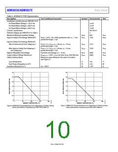
Safety Limiting Values
Transient overvoltage, tTR = 10 sec
VIOSM(TEST) = 10 kV, 1.2 μs rise time, 50 μs, 50% fall time
Maximum value allowed in the event of a failure
(see Figure 6)
VIOTM
VIOSM
8000
6000
VPEAK
VPEAK
Case Temperature
Total Power Dissipation at 25°C
Insulation Resistance at TS
TS
PS
RS
150
2.55
>109
°C
W
Ω
VIO = 500 V
Rev. A | Page 9 of 24

 ADI [ ADI ]