ADM3055E/ADM3057E
Data Sheet
PIN CONFIGURATION AND FUNCTION DESCRIPTIONS
GND
GND
1
2
3
4
5
6
7
8
9
20 GND
ISO
1
1
19
V
ISOOUT
V
18 GND
ISO
CC
V
17 AUX
OUT
IO
ADM3055E/
ADM3057E
RXD
SILENT
TXD
16
V
ISOIN
TOP VIEW
15 GND
2
(Not to Scale)
14 CANH
13 CANL
12 RS
STBY
AUX
IN
GND 10
11 GND
2
1
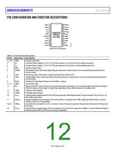
Figure 8. Pin Configuration
Table 12. Pin Function Descriptions
Pin No. Mnemonic Description
1, 2, 10
GND1
VCC
Ground, Logic Side.
3
4
5
6
isoPower Power Supply, 4.5 V to 5.5 V. This pin requires 0.1 µF and 10 µF decoupling capacitors.
iCoupler Power Supply, 1.7 V to 5.5 V. This pin requires 0.01 µF and 0.1 µF decoupling capacitors.
Receiver Output Data.
Silent Mode Select with Input High. Bring this input low or leave the pin unconnected (internal pull-down) for
normal mode.
VIO
RXD
SILENT
7
8
TXD
STBY
Driver Input Data. This pin has a weak internal pull-up resistor to VIO.
Standby Mode Select with Input High. Bring this input low or leave the pin unconnected (internal pull-down) for
normal mode.
9
AUXIN
GND2
RS
Auxiliary Channel Input. This pin sets the AUXOUT output.
Ground, Bus Side.
Slope Control Pin. Short this pin to ground for full speed operation or use a weak pull-down resistor (for example,
47 kΩ) for slope control mode. An input high signal places the CAN transceiver in standby mode.
11, 15
12
13
14
16
CANL
CANH
VISOIN
CAN Low Input/Output.
CAN High Input/Output.
Isolated Power Supply Input for the CAN Transceiver Bus Side Digital Isolator. This pin requires 0.01 µF and 0.1 µF
decoupling capacitors.
17
AUXOUT
GNDISO
VISOOUT
Isolated Auxiliary Channel Output. The state of AUXOUT is latched when STBY is high. By default, AUXOUT is low at
startup or when VIO is unpowered.
Ground for the Isolated DC-to-DC Converter. Connect these pins together through one ferrite bead to PCB ground
(bus side).
Isolated Power Supply Output. This pin requires 0.22 µF and 10 µF capacitors to GNDISO. Connect this pin through a
ferrite bead and short the PCB trace to VISOIN for operation.
18, 20
19
Rev. A | Page 12 of 24

 ADI [ ADI ]