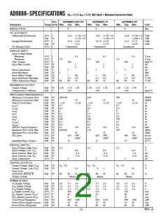
AD9888
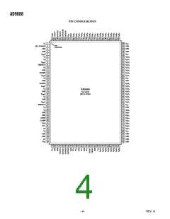
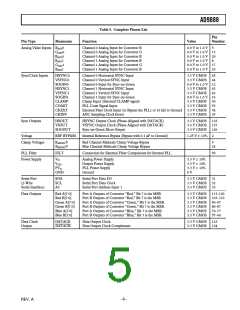
PIN FUNCTION DESCRIPTIONS
Pin
Description
Inputs
R
AIN0
AIN0
BAIN
AIN1
GAIN
AIN1
Channel 0 Analog Input for RED
Channel 0 Analog Input for GREEN
Channel 0 Analog Input for BLUE
Channel 1 Analog Input for RED
Channel 1 Analog Input for GREEN
Channel 1 Analog Input for BLUE
G
0
R
1
B
High-impedance inputs that accept the RED, GREEN, and BLUE channel graphics signals, respectively. (The six
channels are identical and can be used for any colors; colors are assigned for convenient reference.)
They accommodate input signals ranging from 0.5 V to 1.0 V full scale. Signals should be ac-coupled to these pins to
support clamp operation.
HSYNC0
HSYNC1
Channel 0 Horizontal Sync Input
Channel 1 Horizontal Sync Input
These inputs receive a logic signal that establishes the horizontal timing reference and provides the frequency reference
for pixel clock generation.
The logic sense of this pin is controlled by serial register 0Eh Bit 6 (Hsync Polarity). Only the leading edge of Hsync is
used by the PLL. The trailing edge is used for clamp timing only. When HSPOL = 0, the falling edge of Hsync is used.
When HSPOL = 1, the rising edge is active.
The input includes a Schmitt trigger for noise immunity, with a nominal input threshold of 1.5 V.
VSYNC0
VSYNC1
Channel 0 Vertical Sync Input
Channel 1 Vertical Sync Input
These are the inputs for vertical sync.
SOGIN0
SOGIN1
Channel 0 Sync-on-Green Input
Channel 1 Sync-on-Green Input
This input is provided to assist with processing signals with embedded sync, typically on the GREEN channel. The pin is
connected to a high-speed comparator with an internally generated, variable threshold level, which is nominally set to
0.15 V above the negative peak of the input signal.
When connected to an ac-coupled graphics signal with embedded sync, it will produce a noninverting digital output on
SOGOUT. (This is usually a composite sync signal, containing both vertical and horizontal sync information.)
When not used, this input should be left unconnected. For more details on this function and how it should be config-
ured, refer to the Sync-on-Green section.
CLAMP
External Clamp Input
This logic input may be used to define the time during which the input signal is clamped to the reference dc level
(ground for RGB or midscale for YUV). It should be exercised when the reference dc level is known to be present on
the analog input channels, typically during the back porch of the graphics signal. The CLAMP pin is enabled by setting
the external clamp control (register 0Fh, Bit 7) to 1 (default is 0). When disabled, this pin is ignored and the clamp
timing is determined internally by counting a delay and duration from the trailing edge of the HSYNC input. The logic
sense of this pin is controlled by the clamp polarity control (register 0Fh, Bit 6). When not used, this pin must be grounded
and external clamp programmed to 0.
COAST
Clock Generator Coast Input (Optional)
This input may be used to cause the pixel clock generator to stop synchronizing with HSYNC and continue producing
a clock at its current frequency and phase. This is useful when processing signals from sources that fail to produce horizontal
sync pulses when in the vertical interval or that include equalization pulses. The Coast signal is usually not required for
PC-generated signals.
The logic sense of this pin is controlled by 0FH Bit 3 (Coast Polarity).
When not used, this pin may be grounded and Coast Polarity programmed to 1, or tied HIGH (to VD through a 10 kΩ resistor)
and Coast Polarity programmed to 0. The Coast Polarity register bit defaults to 1 at power-up.
CKEXT
External Clock Input (Optional)
This pin may be used to provide an external clock to the AD9888, in place of the clock internally generated from
HSYNC. It is enabled by programming the External clock register to 1 (15H, Bit 0). When an external clock is used, all
other internal functions operate normally. When unused, this pin should be tied through a 10 kΩ resistor to GROUND,
and the External Clock register programmed to 0. The clock phase adjustment still operates when an external clock
source is used.
–6–
REV. A

 ADI [ ADI ]