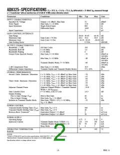
(T = 25؇C, V = 5 V, R = 75 ⍀, V (differential) = 31 dBmV, VOUT measured through
AD8325–SPECIFICATIONS
A
S
L
IN
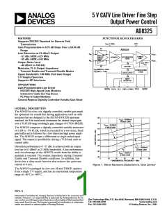
a 1:1 transformer1 with an insertion loss of 0.5 dB @ 10 MHz unless otherwise noted.)
Parameter
Conditions
Min Typ
Max
Unit
INPUT CHARACTERISTICS
Specified AC Voltage
Noise Figure
Output = 61 dBmV, Max Gain
Max Gain, f = 10 MHz
Single-Ended Input
31
dBmV
dB
Ω
13.8
800
1600
2
Input Resistance
Differential Input
Ω
Input Capacitance
pF
GAIN CONTROL INTERFACE
Gain Range
Maximum Gain
Minimum Gain
Gain Scaling Factor
58.45 59.45
29.2 30.0
–30.25 –29.45
0.7526
60.45
30.8
–28.65 dB
dB/LSB
dB
dB
Gain Code = 79 Dec
Gain Code = 0 Dec
OUTPUT CHARACTERISTICS
Bandwidth (–3 dB)
Bandwidth Roll-Off
All Gain Codes
f = 65 MHz
f = 65 MHz
100
1.6
0
MHz
dB
dB
Bandwidth Peaking
Output Noise Spectral Density
Max Gain, f = 10 MHz
–33
dBmV in
160 kHz
dBmV in
160 kHz
dBmV in
160 kHz
dBm
Min Gain, f = 10 MHz
–48
–68
18.5
Transmit Disable Mode, f = 10 MHz
Max Gain, f = 10 MHz
1 dB Compression Point
Differential Output Impedance
Transmit Enable and Transmit Disable Modes
75 20%
Ω
OVERALL PERFORMANCE
Second Order Harmonic Distortion
f = 21 MHz, VOUT = 61 dBmV @ Max Gain
f = 42 MHz, VOUT = 61 dBmV @ Max Gain
f = 65 MHz, VOUT = 61 dBmV @ Max Gain
f = 21 MHz, VOUT = 61 dBmV @ Max Gain
f = 42 MHz, VOUT = 61 dBmV @ Max Gain
f = 65 MHz, VOUT = 61 dBmV @ Max Gain
Adjacent Channel Width = Transmit Channel
Width = 160 KSYM/SEC
–70
–67
–60
–57
–55
–54
–53.8
dBc
dBc
dBc
dBc
dBc
dBc
dBc
Third Order Harmonic Distortion
Adjacent Channel Power
Gain Linearity Error
Output Settling
f = 10 MHz, Code to Code
0.3
dB
Due to Gain Change (TGS
Due to Input Change
Isolation in Transmit Disable Mode
)
Min to Max Gain
60
30
–33
ns
ns
dBc
Max Gain, VIN = 31 dBmV
Max Gain, TXEN = 0 V, f = 42 MHz,
VIN = 31 dBmV
POWER CONTROL
Transmit Enable Settling Time (TON
)
Max Gain, VIN = 0 V
Max Gain, VIN = 0 V
Equivalent Output = 31 dBmV
Equivalent Output = 61 dBmV
300
40
3
ns
ns
mV p-p
mV p-p
Transmit Disable Settling Time (TOFF
)
Between Burst Transients2
50
POWER SUPPLY
Operating Range
Quiescent Current
4.75
123
30
5
5.25
140
10
V
Transmit Enable Mode (TXEN = 1)
Transmit Disable Mode (TXEN = 0)
Sleep Mode
133
35
4
mA
mA
mA
2
7
OPERATING TEMPERATURE
RANGE
–40
+85
°C
NOTES
1TOKO 617DB-A0070 used for above specifications. MACOM ETC-1-IT-15 can be substituted.
2Between Burst Transients measured at the output of a 42 MHz diplexer.
Specifications subject to change without notice.
–2–
REV. 0

 ADI [ ADI ]