AD73360
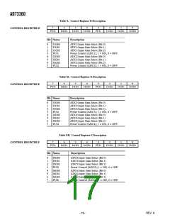
Table XIII. Control Register G Description
7
6
5
4
3
2
1
0
CONTROL REGISTER G
SEEN
RMOD
CH6
CH5
CH4
CH3
CH2
CH1
Bit Name
Description
0
1
2
3
4
5
6
7
CH1
CH2
CH3
CH4
CH5
CH6
Channel 1 Select
Channel 2 Select
Channel 3 Select
Channel 4 Select
Channel 5 Select
Channel 6 Select
RMOD
SEEN
Reset Analog Modulator
Enable Single-Ended Input Mode
Table XIV. Control Register H Description
CONTROL REGISTER H
7
6
5
4
3
2
1
0
INV
TME
CH6
CH5
CH4
CH3
CH2
CH1
Bit Name
Description
0
1
2
3
4
5
6
7
CH1
CH2
CH3
CH4
CH5
CH6
TME
INV
Channel 1 Select
Channel 2 Select
Channel 3 Select
Channel 4 Select
Channel 5 Select
Channel 6 Select
Test Mode Enable
Enable Invert Channel Mode
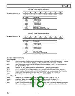
REGISTER BIT DESCRIPTIONS
Control Register A
CRA:0
Data/Program Mode. This bit controls the operating mode of the AD73360. If CRA:1 is 0, then a 0 in this bit
places the part in Program Mode. If CRA:1 is 0, then a 1 in this bit places the part in Data Mode.
CRA:1
Mixed Mode. If this bit is a 0, then the operating mode is determined by CRA:0. If this bit is a 1, then the
part operates in Mixed Mode.
CRA:2
Reserved. This bit is reserved and should be programmed to 0 to ensure correct operation.
CRA:3
SPORT Loop Back. This is a diagnostic mode. This bit should be set to 0 to ensure correct operation.
CRA:4–6
Device Count Bits. These bits tell the AD73360 how many devices are used in a cascade. All devices in the
cascade should be programmed to the same value ensure correct operation. See Table XVIII.
CRA:7
Reset. Writing a 1 to this bit will initiate a software reset of the AD73360.
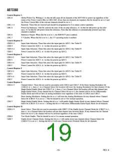
Control Register B
CRB:0–1
CRB:2–3
CRB:4–6
CRB:7
Decimation Rate. These bits are used to set the decimation of the AD73360. See Table VII.
Serial Clock Divider. These bits are used to set the serial clock frequency. See Table VI.
Master Clock Divider. These bits are used to set the Master Clock Divider ratio. See Table V.
Control Echo Enable. Setting this bit to a 1 will cause the AD73360 to write out any control words it receives.
This is used as a diagnostic mode. This bit should be set to 0 for correct operation in Mixed Mode or Data Mode.
REV. B
–17–

 ADI [ ADI ]