AD73360
SPORT Register Maps
setting to ensure correct operation (this is shown in the pro-
gramming examples). The other six registers; CRC through
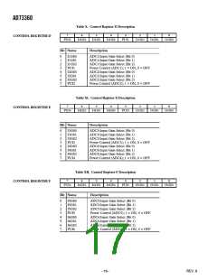
CRH are used to hold control settings for the Reference, Power
Control, ADC channel and PGA sections of the device. It is
not necessary that the contents of CRC through CRH on
each AD73360 are similar. Control registers are written to on
the negative edge of SCLK.
There are eight control registers for the AD73360, each eight
bits wide. Table V shows the control register map for the
AD73360. The first two control registers, CRA and CRB, are
reserved for controlling the SPORT. They hold settings for
parameters such as bit rate, internal master clock rate and de-
vice count. If multiple AD73360s are cascaded, registers CRA
and CRB on each device must be programmed with the same
Table V. Control Register Map
Description Type
Address (Binary)
Name
Width
Reset Setting (Hex)
000
001
010
011
100
101
110
111
CRA
CRB
CRC
CRD
CRE
CRF
CRG
CRH
Control Register A
Control Register B
Control Register C
Control Register D
Control Register E
Control Register F
Control Register G
Control Register H
R/W
R/W
R/W
R/W
R/W
R/W
R/W
R/W
8
8
8
8
8
8
8
8
0x00
0x00
0x00
0x00
0x00
0x00
0x00
0x00
Table VI. Control Word Description
15
14
13
12
11
10
9
8
7
6
5
4
3
2
1
0
C/D
R/W
DEVICE ADDRESSS
REGISTER ADDRESS
REGISTER DATA
Control
Frame
Description
Bit 15
Control/Data
When set high, it signifies a control word in Program or Mixed Program/Data Modes. When set
low, it signifies an invalid control word in Program Mode.
Bit 14
Read/Write
When set low, it tells the device that the data field is to be written to the register selected by the
register field setting provided the address field is zero. When set high, it tells the device that the
selected register is to be written to the data field in the serial register and that the new control
word is to be output from the device via the serial output.
Bits 13–11
Device Address
This 3-bit field holds the address information. Only when this field is zero is a device selected. If
the address is not zero, it is decremented and the control word is passed out of the device via the
serial output.
Bits 10–8
Bits 7–0
Register Address
Register Data
This 3-bit field is used to select one of the eight control registers on the AD73360.
This 8-bit field holds the data that is to be written to or read from the selected register provided
the address field is zero.
–14–
REV. B

 ADI [ ADI ]