AD73360
Decimation Filter
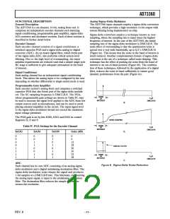
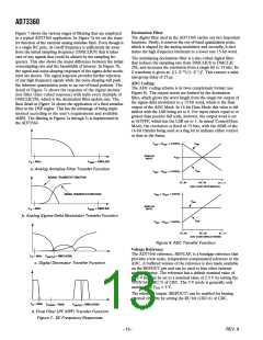
Figure 7 shows the various stages of filtering that are employed
in a typical AD73360 application. In Figure 7a we see the trans-
fer function of the external analog antialias filter. Even though it
is a single RC pole, its cutoff frequency is sufficiently far away
from the initial sampling frequency (DMCLK/8) that it takes
care of any signals that could be aliased by the sampling fre-
quency. This also shows the major difference between the initial
oversampling rate and the bandwidth of interest. In Figure 7b,
the signal and noise-shaping responses of the sigma-delta modu-
lator are shown. The signal response provides further rejection
of any high frequency signals while the noise-shaping will push
the inherent quantization noise to an out-of-band position. The
detail of Figure 7c shows the response of the digital decima-
tion filter (Sinc-cubed response) with nulls every multiple of
DMCLK/256, which is the decimation filter update rate. The
final detail in Figure 7d shows the application of a final antialias
filter in the DSP engine. This has the advantage of being imple-
mented according to the user’s requirements and available
MIPS. The filtering in Figures 7a through 7c is implemented in
the AD73360.
The digital filter used in the AD73360 carries out two important
functions. Firstly, it removes the out-of-band quantization noise,
which is shaped by the analog modulator and secondly, it deci-
mates the high frequency bitstream to a lower rate 15-bit word.
The antialiasing decimation filter is a sinc-cubed digital filter
that reduces the sampling rate from DMCLK/8 to DMCLK/
256, and increases the resolution from a single bit to 15 bits. Its
Z transform is given as: [(1–Z–32)/(1–Z–1)]3. This ensures a mini-
mal group delay of 25 µs.
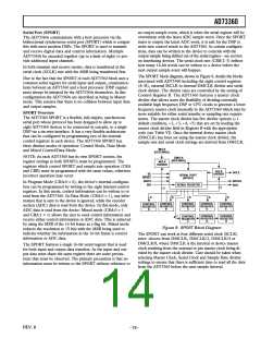
ADC Coding
The ADC coding scheme is in twos complement format (see
Figure 8). The output words are formed by the decimation
filter, which grows the word length from the single-bit output of
the sigma-delta modulator to a 15-bit word, which is the final
output of the ADC block. In 16-bit Data Mode this value is left
shifted with the LSB being set to 0. For input values equal to or
greater than positive full scale, however, the output word is set
at 0x7FFF, which has the LSB set to 1. In mixed Control/Data
Mode, the resolution is fixed at 15 bits, with the MSB of the
16-bit transfer being used as a flag bit to indicate either control
or data in the frame.
V
V
+ (V
REF
INN
REF
ANALOG
INPUT
V
REF
F
= 4kHz
F
= DMCLK/8
SINIT
B
a. Analog Antialias Filter Transfer Function
V
INP
V
– (V
REF
REF
SIGNAL TRANSFER FUNCTION
10...00
00...00
01...11
ADC CODE DIFFERENTIAL
V
+ (V
REF
NOISE TRANSFER FUNCTION
REF
V
INN
ANALOG
INPUT
F
= 4kHz
F
= DMCLK/8
B
SINIT
b. Analog Sigma-Delta Modulator Transfer Function
V
INP
V
REF
REF
10...00
00...00
ADC CODE SINGLE-ENDED
01...11
Figure 8. ADC Transfer Function
Voltage Reference
The AD73360 reference, REFCAP, is a bandgap reference that
provides a low noise, temperature-compensated reference to the
ADC. A buffered version of the reference is also made available
on the REFOUT pin and can be used to bias other external
analog circuitry. The reference has a default nominal value of
1.25 V but can be set to a nominal value of 2.5 V by setting the
5VEN bit (CRC:7) of CRC. The 5 V mode is generally only
usable when VDD = 5 V.
F
= 4kHz
F
= DMCLK/256
B
SINTER
c. Digital Decimator Transfer Function
The reference output (REFOUT) can be enabled for biasing
external circuitry by setting the RU bit (CRC:6) of CRC.
F
= 4kHz
F
= 8kHz
F
= DMCLK/256
B
SFINAL
SINTER
d. Final Filter LPF (HPF) Transfer Function
Figure 7. DC Frequency Responses
–12–
REV. B

 ADI [ ADI ]