Data Sheet
AD5232
100
75
Table 11. Nominal Individual Segment Resistor Values (Ω)
Segmented Resistor Size
for RAB End-to-End Values
Device
Resolution Version
8-Bit 78.10
10 kΩ
50 kΩ
Version
100 kΩ
Version
390.5
781.0
50
25
0
PROGRAMMING THE VARIABLE RESISTOR
Rheostat Operation
The nominal resistances of the RDACx between Terminal A and
Terminal B are available with values of 10 kΩ, 50 kΩ, and 100 kΩ.
The final digits of the part number determine the nominal
resistance value; for example, 10 kΩ = 10; 100 kΩ = 100. The
nominal resistance (RAB) of the AD5232 VR has 256 contact
points accessed by Wiper Terminal W, plus the Terminal B contact.
The 8-bit data-word in the RDACx latch is decoded to select
one of the 256 possible settings.
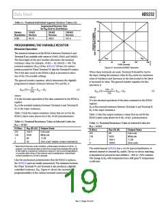
R
R
WA
WB
0
64
128
192
258
CODE (Decimal)
Figure 41. Symmetrical RDAC Operation
When these terminals are used, Terminal B should be tied to
the wiper. Setting the resistance value for RWA starts at a maximum
value of resistance and decreases as the data loaded in the latch
is increased in value. The general transfer equation for this
operation is
The general transfer equation, which determines the digitally
programmed output resistance between Wx and Bx, is
D
256
256 D
RWB (D)
RAB RW
(1)
RWA (D)
RAB RW
(2)
256
where:
where:
D is the decimal equivalent of the data contained in the RDACx
register.
RAB is the nominal resistance between Terminal A and Terminal B.
RW is the wiper resistance.
D is the decimal equivalent of the data contained in the RDAC
register.
RAB is the nominal resistance between Terminal A and Terminal B.
RW is the wiper resistance.
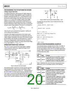
Table 12 lists the output resistance values that are set for the
RDACx latch codes shown for 8-bit, 10 kΩ potentiometers.
Table 13 lists the output resistance values that are set for the
RDACx latch codes shown for 8-bit, 10 kΩ potentiometers.
Table 12. Nominal Resistance Value at Selected Codes for
RAB = 10 kΩ
Table 13. Nominal Resistance Value at Selected Codes for
RAB = 10 kΩ
D (Dec)
RWB (D) (Ω) Output State
D (Dec)
RWA (D) (Ω)
Output State
Full scale
Midscale
1 LSB
255
128
1
10011
5050
89
Full scale
Midscale
1 LSB
255
128
1
89
5050
10011
10050
0
50
Zero scale1 (wiper contact resistance)
0
Zero scale
1 Note that in the zero-scale condition, a finite wiper resistance of 50 Ω is
present. Care should be taken to limit the current flow between Wx and Bx
in this state to a maximum continuous value of 2 mA to avoid degradation
or possible destruction of the internal switch metallization. Intermittent
current operation to 20 mA is allowed.
The multichannel AD5232 has a 0.2% typical distribution of
internal channel-to-channel RBA match. Device-to-device matching
is dependent on process lot and exhibits a −40% to +20% variation.
The change in RBA with temperature has a 600 ppm/°C temperature
coefficient.
Like the mechanical potentiometer that the RDACx replaces,
the AD5232 parts are totally symmetrical. The resistance between
the Wiper Terminal W and Terminal A also produces a digitally
controlled resistance, RWA. Figure 41 shows the symmetrical
programmability of the various terminal connections.
Rev. C | Page 19 of 24

 ADI [ ADI ]