AD5232
Data Sheet
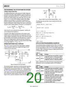
Command bits are identified as Cx, address bits are Ax, and
data bits are Dx. The command instruction codes are defined
in Table 8. The SDO output shifts out the last eight bits of data
clocked into the serial register for daisy-chain operation, with
the following exception: after Command Instruction 9 or Com-
mand Instruction 10, the selected internal register data is present
in Data Byte 0. The command instructions following Command
Instruction 9 and Command Instruction 10 must be full 16-bit
data-words to completely clock out the contents of the serial
register. The RDACx register is a volatile scratch pad register
that is refreshed at power-on from the corresponding nonvol-
atile EEMEMx register. The increment, decrement, and shift
command instructions ignore the contents of Data Byte 0 in the
shift register. Execution of the operation noted in Table 8 occurs
CS
when the
strobe returns to logic high. Execution of an NOP
instruction minimizes power dissipation.
Table 7. 16-Bit Serial Data Word
MSB
LSB
B0
B15
B14
B13
B12
B11
B10
B9
B8
B7
B6
B5
B4
B3
B2
B1
C3
C2
C1
C0
A3
A2
A1
A0
D7
D6
D5
D4
D3
D2
D1
D0
Table 8. Instruction/Operation Truth Table
Instruction Byte 1
Data Byte 0
Comm.
Inst.
B15
B8
B7
B0
No.
C3
0
0
C2
0
0
C1 C0
A3 A2 A1 A0 D7 D6 D5 D4 D3 D2 D1 D0
Operation
0
1
0
0
0
1
X
0
X
0
X
0
X
A0
X
X
X
X
X
X
X
X
X
X
X
X
X
X
X
X
No operation (NOP). Do nothing.
Write contents of EEMEM (A0) to
the RDAC (A0) register. This com-
mand leaves the device in the read
program power state. To return
the part to the idle state, perform
Command Instruction 0 (NOP).
2
0
0
1
0
0
0
0
A0
X
X
X
X
X
X
X
X
Save wiper setting. Write
contents of RDAC (ADDR) to
EEMEM (A0).
3
4
5
0
0
0
0
1
1
1
0
0
1
0
1
ADDR
D7 D6 D5 D4 D3 D2 D1 D0
Write contents of Serial Register
Data Byte 0 to EEMEM (ADDR).
Decrement 6 dB right shift con-
0
0
0
A0
X
X
X
X
X
X
X
X
X
X
X
X
X
X
X
X
X
tents of RDAC (A0). Stops at all 0s.
X
X
X
Decrement all 6 dB right shift
contents of all RDAC registers.
Stops at all 0s.
6
7
8
0
0
1
1
1
0
1
1
0
0
1
0
0
X
0
0
X
0
0
X
0
A0
X
X
X
X
X
X
X
X
X
X
X
X
X
X
X
X
X
X
X
X
X
X
X
X
X
Decrement contents of RDAC (A0)
by 1. Stops at all 0s.
Decrement contents of all RDAC
registers by 1. Stops at all 0s.
Reset. Load all RDACs with their
corresponding, previously saved
EEMEM values.
0
9
1
1
1
1
1
0
0
0
1
1
0
1
1
0
0
1
0
1
0
1
ADDR
X
X
X
X
X
X
X
X
X
X
X
X
X
X
X
X
Write contents of EEMEM(ADDR)
to Serial Register Data Byte 0.
Write contents of RDAC (A0) to
Serial Register Data Byte 0.
Write contents of Serial Register
Data Byte 0 to RDAC (A0).
Increment 6 dB left shift contents
of RDAC (A0). Stops at all 1s.
10
11
12
13
0
0
0
X
0
0
0
X
0
0
0
X
A0
A0
A0
X
D7 D6 D5 D4 D3 D2 D1 D0
X
X
X
X
X
X
X
X
X
X
X
X
X
X
X
X
Increment all 6 dB left shift
contents of all RDAC registers.
Stops at all 1s.
14
15
1
1
1
1
1
1
0
1
0
0
0
A0
X
X
X
X
X
X
X
X
X
X
X
X
X
X
X
X
X
Increment contents of RDAC (A0)
by 1. Stops at all 1s.
Increment contents of all RDAC
registers by 1. Stops at all 1s.
X
X
X
Rev. C | Page 16 of 24

 ADI [ ADI ]