AD5232
Data Sheet
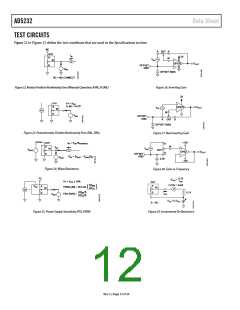
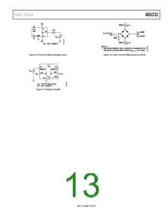
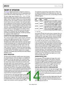
TEST CIRCUITS
Figure 22 to Figure 32 define the test conditions that are used in the Specifications section.
NC
A
DUT
B
DUT
I
W
5V
OP279
A
W
V
W
IN
V
OUT
OFFSET
GND
B
V
MS
OFFSET BIAS
NC = NO CONNECT
Figure 22. Resistor Position Nonlinearity Error (Rheostat Operation; R-INL, R-DNL)
Figure 26. Inverting Gain
5V
DUT
A
W
V+ = V
DD
1LSB = V+/2
N
OP279
V
OUT
V
IN
V+
W
B
V
MS
OFFSET
GND
A
DUT
B
OFFSET BIAS
Figure 23. Potentiometer Divider Nonlinearity Error (INL, DNL)
Figure 27. Noninverting Gain
+15V
A
DUT
A
I
= V /R
DD NOMINAL
W
W
V
W
W
V
IN
V
DUT
MS2
V
OP42
B
OUT
B
OFFSET
GND
R
= [V
MS1
– V ]/I
W
MS2
W
V
MS1
2.5V
–15V
Figure 24. Wiper Resistance
Figure 28. Gain vs. Frequency
V
0.1V
A
R
=
SW
I
V+ = V ± 10%
DD
SW
DUT
A
ΔV
CODE = 0x00
MS
V
A
B
DD
PSRR (dB) = 20 LOG
W
(ΔV )
W
DD
V+
~
+
–
ΔV
ΔV
%
%
MS
B
0.1V
I
PSS (%/%) =
V
SW
MS
DD
V
SS
TO V
DD
A = NC
Figure 25. Power Supply Sensitivity (PSS, PSRR)
Figure 29. Incremental On Resistance
Rev. C | Page 12 of 24

 ADI [ ADI ]