BRIGHT
Microelectronics
Inc.
BM29F400T/BM29F400B
Multiple sectors can be erased simultaneously by writing the sixth bus cycle command of the Sector
Erase command for each sector to be erased. The time between initiation of the next Sector Erase
m
command must be less than 80 S to guarantee acceptance of the command by the internal state
machine. The time-out window can be monitored via the write operation status pin DQ3 (refer to the
Write Operation Status section for Sector Erase Timer operation). It is recommended that CPU
interrupts be disabled during this time to ensure that the subsequent Sector Erase commands can be
m
initiated within the 100 S window. The interrupts can be re-enabled after the last Sector Erase
command is written. As mentioned above, an internal device timer will initiate the Sector Erase
m ± WE
m
m
operation 100
S
20% (80 S to 120 S) from the rising edge of the last pulse. Sector Erase
Timer Write Operation Status pin (DQ3) can be used to monitor time out window. If another falling
WE
edge of the
occurs within the 100 mS time-out window, the internal device timer is reset.
Loading the sector erase buffer may be done in any sequence and with any number of sectors.
Any command other than Sector Erase or Erase Suspend during this period and afterwards will
RESET
the device to read mode, ignoring the previous command string. Resetting the device with a
RESET
hardware
after it has begun execution of a Sector Erase operation will result in the data in
the operated sectors being undefined and may be unrecoverable. In this case, restart the Sector
Erase operation on those sectors and attempt to allow them to complete the Erase operation.
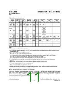
Command Definitions
Device operations are selected by writing specific address and data sequences in to the Command
register. Writing incorrect addresses and data values or writing them in the improper sequence will
RESET
the device to Read mode. Table 5 defines the valid register command sequences. Either of
RESET
the two Read/Reset commands will
the device (when applicable).
Data
During Sector Erase operation, data bit DQ7 shows a logical "0". This operation is known as
Polling. Sector Erase operation is complete when data on DQ7 is a logical "1" (see Write Operation
Status section) at which time the device returns to read mode. At this time, the address pins are no
longer latched. Note that Data Polling must be performed at a sector address within any of the
sectors being erased and not a protected sector to ensure that DQ7 returns a logical "1" upon
completion of the Sector Erase operation.
Figure 2 illustrates the Sector Erase Algorithm using typical command strings and bus operations.
During execution of the Sector Erase command, only the Erase Suspend and Erase Resume
RESET
commands are allowed. All other commands will
the device to read mode.
Note: Do not attempt to write an invalid command sequence during the sector erase operation. Doing so will terminate the sector
erase operation and the device will /RESET to the read mode.
- 10 -

 WINBOND [ WINBOND ]