BRIGHT
Microelectronics
Inc.
Preliminary BM29F040
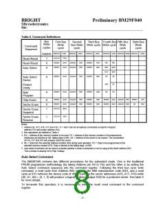
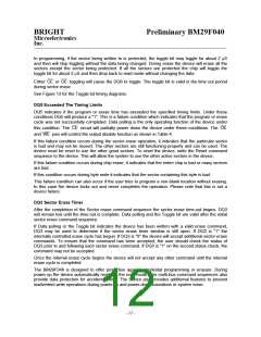
Table 6. Command Definitions
Bus
First Bus
Write
cycle
Second
Third Bus Fourth Bus Fifth Bus
Sixth Bus
Write
cycle
Write
Bus Write Write cycle Write cycle Write
Command
Sequence
cycles
cycle
cycle
Address Data
Address Data
Address Data
Address Data Address Data Address
Data
required
XXXXH
5555H
5555H
F0H
AAH
AAH
1
4
4
Read /Reset
Read /Reset
Auto Select
2AAAH
2AAAH
55H
55H
5555H
5555H
F0H
90H
RA
00H
01H
SA
RD
ADH
40H
00
5555H
AAH
2AAAH
55H
5555H
90H
4
Auto Select
Sector
X02
PA
01
Protect
Verify
5555H
AAH
2AAAH
55H
5555H
A0H
PD
4
Byte
Program
5555H
5555H
XXXXH
AAH
AAH
B0H
2AAAH
2AAAH
55H
55H
5555H
5555H
80H
80H
5555H AAH 2AAAH 55H 5555H
5555H AAH 2AAAH 55H SA
10H
30H
6
6
1
Chip Erase
Sector Erase
Sector Erase
Suspend
XXXXH
30H
1
Sector Erase
Resume
Notes:
1. Address bit A15, A16, A17 and A18 = X = don¢t care for all address commands except for Program
address (PA) and sector address (SA).
2. Bus operations are defined in Table 4.
3. RA = Address of the memory location to be read. PA = Address of the memory location to be programmed.
Addresses are latched on the falling edge of WE. SA = Address of the sector to be erased. The combination
of A16, A17 and A18 will uniquely select the sector.
4. RD = Data from the selected address location (RA) during read operation. PD = Data to be programmed at the
selected memory location (PA). Data is latched at the falling edge of /WE.
5. Auto select command can be used to evaluate whether a block is protected or not by using at the fourth address 02H.
This is similar to placing A9 to High Voltage.
Auto Select Command
The BM29F040 contains two different procedures for the autoselect mode. One is the traditional
PROM programmer methodology (by taking Address pin A9 to VID) and the other is by writing the
Auto Select command sequence into the command register. Following the third bus cycle write
command, a read cycle from Address 00H retrieves the BMI manufacturer code ADH, and a read
cycle at 01H retrieves the device code of 40H. Scanning the sector addresses (A16, A17, A18) while
(A6, A1, A0) = (0, 1, 0) will produce a logical at device output DQ0 for a protected sector. See table 5
for more details.
To terminate this operation, it is necessary to write the read/ reset command to the command
register.
- 8 -

 WINBOND [ WINBOND ]