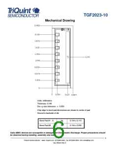
TGF2023-10
Table IV
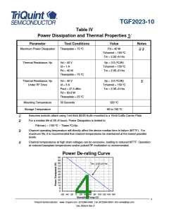
Power Dissipation and Thermal Properties 1/
Parameter
Test Conditions
Value
Notes
Maximum Power Dissipation
Tbaseplate = 70 ºC
Pd = 40 W
2/ 3/
Tchannel = 150 ºC
Tm = 2.0E+6 Hrs
Thermal Resistance, θjc
Vd = 40 V
θjc = 2.0 (ºC/W)
Tchannel = 150 ºC
Tm = 2.0E+6 Hrs
Id = 1 A
Pd = 40 W
Tbaseplate = 75 ºC
Thermal Resistance, θjc
Vd = 40 V
θjc = 2.0 (ºC/W)
Tchannel = 150 ºC
Tm = 2.0E+6 Hrs
4/
Under RF Drive
Id = 3 A
Pout = 47.5 dBm
Pd = 63.8 W
Tbaseplate = 23 ºC
Mounting Temperature
Storage Temperature
30 Seconds
320 ºC
-65 to 150 ºC
1/
2/
Assumes eutectic attach using 1mil thick 80/20 AuSn mounted to a 10mil CuMo Carrier Plate
For a median life of 2E+6 hours, Power Dissipation is limited to
Pd(max) = (150 ºC – Tbase ºC)/θjc.
3/
4/
Channel operating temperature will directly affect the device median time to failure (MTTF). For
maximum life, it is recommended that channel temperatures be maintained at the lowest possible
levels.
Channel temperatures at high drain voltages can be excessive, leading to reduced MTTF. Operation
at reduced baseplate temperatures and/or pulsed RF modulation is recommended.
Power De-rating Curve
96
88
80
Tm= 2.0E+6 Hrs
72
64
56
48
40
32
24
16
8
0
-60 -40 -20
0
20 40 60 80 100 120 140 160
Baseplate Temp (C)
4
TriQuint Semiconductor: www. triquint.com (972)994-8465 Fax (972)994-8504 Info-mmw@tqs.com
Dec 2008 © Rev A

 TRIQUINT [ TRIQUINT SEMICONDUCTOR ]