FEDL87V2107-01
OKI Semiconductor
ML87V2107
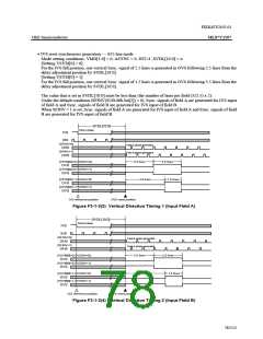
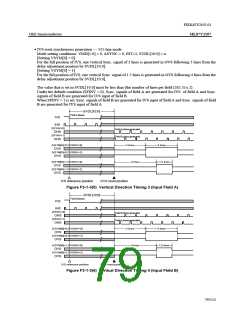
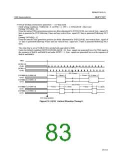
• IVS reset synchronous generation --- 525-line mode
Mode setting conditions: VMD[1:0] = 0, ASYNC = 0, INT=1, SVDL[10:0] = n
[Setting VSYM[0] = 0]
For the fall position of IVS, one vertical Sync. signal of 3 lines is generated in OVS following 3 lines from the
delay adjustment position by SVDL[10:0].
[Setting VSYM[0] = 1]
For the fall position of IVS, one vertical Sync. signal of 1.5 lines is generated in OVS following 4 lines from the
delay adjustment position by SVDL[10:0].
The value that is set in SVDL[10:0] must be less than (the number of lines per field (262.5) x 2).
Under the default condition (SFINV = 0), Sync. signals of field A are generated for IVS of field A and Sync.
signals of field B are generated for IVS input of field B.
When SFINV = 1 is set, Sync. signals of field B are generated for IVS input of field A and Sync. signals of field
B are generated for IVS input of field A
SVDL[10:0]
Field A phase
IVS
IHS
[SFINV=0]
Field A phase generated
OHS
[SFINV=1]
Field B phase generated
OHS
[VSYM[0]=0,OVSINV=0]
OVS
3 lines
3 lines
[VSYM[0]=0,OVSINV=1]
OVS
[VSYM[0]=1,OVSINV=0]
OVS
4 lines
1.5 lines
[VSYM[0]=1,OVSINV=1]
OVS
IVS reference position
OVS reset position
Figure F3-1-3(5) Vertical Direction Timing 3 (Input Field A)
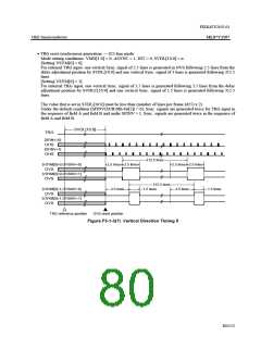
SVDL[10:0]
Field B phase
IVS
IHS
[SFINV=0]
Field B phase generated
Field A phase generated
OHS
[SFINV=1]
OHS
[VSYM[0]=0,OVSINV=0]
OVS
3 lines
3 lines
[VSYM[0]=0,OVSINV=1]
OVS
[VSYM[0]=1,OVSINV=0]
OVS
4 lines
1.5 lines
[VSYM[0]=1,OVSINV=1]
OVS
IVS reference position
OVS reset position
Figure F3-1-3(6) Vertical Direction Timing 4 (Input Field B)
79/152

 OKI [ OKI ELECTRONIC COMPONETS ]