EM785830AA
8-bit Micro-controller
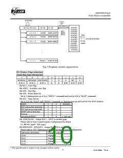
R5(PAGE)
CALL
and
INTERRUPT
STACK1
STACK2
STACK3
STACK4
STACK5
STACK6
STACK7
STACK8
A13 A12 A11 A10
A9 A8
A7~A0
RET
RETL
RETI
0 0 0 0
0 0 0 1
PAGE0 00000~003FF
PAGE1 00400~007FF
store
ACC,R3,R5(PAGE)
0 0 1 0
PAGE2 00800~00BFF
restore
STACK9
STACK10
STACK11
STACK12
:
:
:
1 1 1 1
PAGE15 05400~057FF
Fig.3 Program counter organization
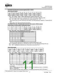
R3 (Status, Page selection)
(Status flag, Page selection bits)
7
6
5
4
T
R
3
P
R
2
Z
1
0
RPAGE1 RPAGE0 IOCPAGE
R/W-0 R/W-0 R/W-0
Bit 0(C) : Carry flag
DC
R/W
C
R/W
R/W
Bit 1(DC) : Auxiliary carry flag
Bit 2(Z) : Zero flag
Bit 3(P) : Power down bit
Set to 1 during power on or by a "WDTC" command and reset to 0 by a "SLEP" command.
Bit 4(T) : Time-out bit
Set to 1 by the "SLEP" and "WDTC" command, or during power up and reset to 0 by WDT timeout.
EVENT
T
P
REMARK
WDT wake up from sleep mode
WDT time out (not sleep mode)
/RESET wake up from sleep
Power up
0
0
1
1
x
0
1
0
1
Low pulse on /RESET
X
x : don't care
Bit 5(IOCPAGE) : change IOC5 ~ IOCE to another page
Please refer to Fig.4 control register configuration for details.
0/1 Î IOC page0 / IOC page1
Bit 6(RPAGE0 ~ RPAGE1) : change R5 ~ RE to another page
Please refer to VII.1 Operational registers for detail register configuration.
(RPAGE1,RPAGE0)
R page # selected
R page 0
(0,0)
(0,1)
(1,0)
(1,1)
R page 1
R page 2
R page 3
__________________________________________________________________________________________________________________________________________________________________
* This specification is subject to be changed without notice.
8
12/1/2004 V1.6

 ELAN [ ELAN MICROELECTRONICS CORP ]