EM73P362
4-BIT MICRO-CONTROLLER FOR LCD PRODUCT
TBI1:
LDIA
OUTA
INA
#00H
P17
P3
;disable RFO before reading the counter value
;store the counter value to RAM[00] - RAM[04]
STA
INA
00H
P5
STA
01H
LDATBL
STA
LDATBM
STA
LDATBH
STA
02H
03H
04H
TBIEND: RTI
;main program
MAIN:
STD
#00H,RFCON
#0001B
P18
LDIA
OUTA
LDIA
EXAE
EICIL
LDIA
OUTA
LDIA
OUTA
:
;P4.0 (RX) output
;enable timebase interrupt
#0010B
0
#1111B
P17
#1101B
P25
;enable RFO mode, the window gate width of RFO=214/XIN sec.
;enable timebase, interrupt frequency : XIN / 215 Hz
Melody mode
TONE
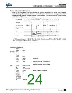
The P4.0/
and TONE pins will output the square wave in the melody mode. When the CPU is not
TONE
in the melody mode, the P4.0/
is high and TONE is low.
The 8-bit tone frequency register is P5 and P3. The tone frequency will be changed when users output
the different data to P3. Thus, the data must be output to P5 before P3 when users want to change the
8-bit tone frequency (TF).
P5
P3
3
2
1
0
3
2
1
0
Initial value : 0000 0000 ( TF )
Higher nibble register
Lower nibble register
** FTONE = [ (XIN / 2X) / (100H - TF) ] / 2, TF = 0 ~ 255
** Example : XIN = 32KHz, RATE = 01, TF = 11110000B = 0F0H.
FTONE = [ (32K Hz / 22) / (100H - 0F0H) ] / 2 = 256 Hz.
* This specification are subject to be changed without notice.
11.1.2001
25

 ELAN [ ELAN MICROELECTRONICS CORP ]