EM73P362
4-BIT MICRO-CONTROLLER FOR LCD PRODUCT
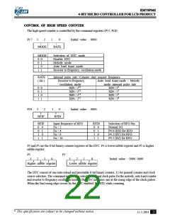
CONTROL OF HIGH SPEED COUNTER
The high speed counter is controlled by the command registers (P17, P18) :
P17
3
2
1
0
Initial value : 0000
MODE
RATE
MODE
0 0
Selection of HTC mode
Disable HTC
0 1
Melody mode
1 0
1 1
Auto load timer mode
Resistor to frequency oscillation mode
RATE
( Hz )
Internal pulse rate / Counter start request frequency
Resistor to frequency
oscillation mode
XIN / 210
Auto load timer mode / Melody
mode internal pulse rate
0 0
0 1
1 0
1 1
XIN / 20
XIN / 212
XIN / 22
XIN / 214
XIN / 24
XIN / 215
XIN / 26
P18
3
2
1
0
Initial value : 0000
RFIP
RFIN
RFIP
0 0
0 1
1 0
1 1
Input frequency of RFO
RFIN
0 0
0 1
1 0
1 1
Selection of RFO Pin
Normal I/O
P4.0 (RX) for RFO
P4.2 (RY) for RFO
P4.3 (RZ) for RFO
F
F
F
F
RF / 2
RF / 4
RF / 8
RF / 16
P3 and P5 are the 8-bit binary counter registers of the HTC. P3 is lower nibble register and P5 is higher
nibble register.
P5
P3
3
2
1
0
3
2
1
0
Initial value : 0000 0000
Higher nibble register
Lower nibble register
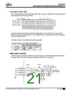
The HTC consist of one auto-reload and presetable 8-bit binary counter, 12-bit general counter and clock
source selectors. The command register can select the internal clock pulse for the melody, auto load counter
and resistor to frequency oscillation modes. The HTC increases one at the rising edge of the clock pulses.
When the first rising edge occurs by the HTC enabled, the HTC starts counting.
* This specification are subject to be changed without notice.
22
11.1.2001

 ELAN [ ELAN MICROELECTRONICS CORP ]