Application Information: continued
be used in synchronized operation, the inductor value converter and performs the same function as the flyback
should be recalculated to work with the slope compensa-
tion ramp reduced to 67% of the normal value.
winding above.
A flyback winding from a forward transformer can also be
used to power VCC. Ideally the transformer volt-second
product of a forward converter would be constant over the
range of line voltages and load currents; and the trans-
former inductance could be chosen to store the required
level of energy during each cycle to power VCC. Even
though the flyback energy is not directly regulated it
would remain constant. Unfortunately in a real converter
there are many non-ideal effects that degrade regulation.
Transformer inductance varies, converter frequency varies,
energy stored in primary leakage inductance varies with
output current, stray transformer capacitances and various
parasitics all effect the level of energy available for VCC. If
too little energy is provided to VCC, the bootstrapping cir-
cuit must provide power and efficiency will be reduced. If
too much energy is provided VCC rises and may damage
the controller. If this approach is taken the circuit must be
carefully designed and component values must be con-
trolled for good regulation.
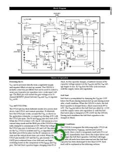
Powering the CS5124/6 from a Transformer Winding
There are numerous ways to power the CS5124/6 from a
transformer winding to enable the converter to be operated
at high efficiency over a wide input range. Two ways are
shown in the application circuits.
The CS5124 application circuit (main application diagram)
is a flyback converter that uses a second flyback winding
to power VCC. R4 improves VCC regulation with load
changes by snubbing the turn off spike. Once the turn off
spike has subsided the voltage of this winding is voltage
proportional to the voltage on the main flyback winding.
This voltage is regulated because the main winding is
clamped by the regulated output voltage.
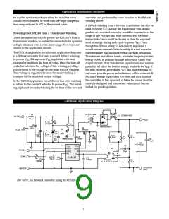
In the CS5126 application circuit (below) an extra winding
is added to the forward inductor to power VCC. This wind-
ing is phased to conduct during the off time of the forward
Additional Application Diagram
CTX15-14526
T2
L1
CTX15-14527
T1
36-75V
IN
10µH
5V
OUT
R1
R2
39k
200k
Q1
C2
F2T493
1.5µF,
100V
MBRB2060CT
C3
Q2
IRF634
D2
0.2µF, 100V
D3
C1
1.5µF,
100V
11V
R6
17.4k
R4
0.2Ω
1/4W
C12
.01µF
R3
R7
2k
C5
1µF,
25V
C6
390pF
30.1k
MMBD6100L
C8
47µF
C7
47µF
C9
.01µF
VCC
UVLO
Gnd
U2
GATE
IS
ENABLE
SYNC
SYNC
SS
VFB
R9
R10
10k
C11
0.1µF
CS5126
C10
1000pF
10k
C4
TPS5908
R8
10.0k
1000pF
ISOLATED
RTN
48VRTN
48V to 5V, 5A forward converter using the CS5126
9

 CHERRY [ CHERRY SEMICONDUCTOR CORPORATION ]