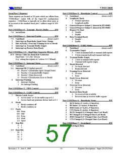
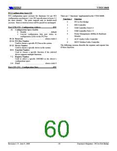
VT82C686B
Function 0 Registers - PCI to ISA Bridge
ISA Bus Control
All registers are located in the function 0 PCI configuration
space of the VT82C686B. These registers are accessed
through PCI configuration mechanism #1 via I/O address
CF8/CFC.
Offset 40 - ISA Bus Control............................................. RW
ISA Command Delay
7
6
5
4
3
2
1
0
0
1
Normal................................................... default
Extra
Extended ISA Bus Ready
PCI Configuration Space Header
0
1
Disable................................................... default
Enable
Offset 1-0 - Vendor ID = 1106h.........................................RO
Offset 3-2 - Device ID = 0686h ..........................................RO
Offset 5-4 - Command.......................................................RW
ISA Slave Wait States
0
1
4 Wait States.......................................... default
5 Wait States
Chipset I/O Wait States
........................................ always reads 0
Address / Data Stepping
15-8 Reserved
7
0
1
2 Wait States.......................................... default
4 Wait States
0
1
Disable
Enable ....................................................default
........................................ always reads 0
I/O Recovery Time
0
1
Disable................................................... default
Enable
6-4 Reserved
.....Normally RW†, default = 0
Special Cycle Enable
3
2
1
0
Extend-ALE
........................................ always reads 1
Bus Master
0
1
Disable................................................... default
Enable
.................. Normally RO†, reads as 1
Memory Space
...................... Normally RO†, reads as 1
I/O Space
ROM Wait States
† If the Rx46[4] test bit is set, access to bits 0, 1, and 3 above
is reversed: bit-3 becomes read only (reading back 1) and bits
0-1 become read / write (with a default of 1).
0
1
1 Wait State ........................................... default
0 Wait States
ROM Write
0
1
Disable................................................... default
Enable
Offset 7-6 - Status...........................................................RWC
....................write one to clear
...................... always reads 0
.................write one to clear
..................write one to clear
..................write one to clear
15 Detected Parity Error
14 Signalled System Error
13 Signalled Master Abort
12 Received Target Abort
11 Signalled Target Abort
Offset 41 - ISA Test Mode................................................ RW
7
6
Bus Refresh Arbitration (do not program) default=0
I/O Recovery Time
0
Normal (13 BCLKs) .............................. default
1
Medium (8 BCLKs)
.................... fixed at 01 (medium)
10-9 DEVSEL# Timing
5
Port 92 Fast Reset
.......................... always reads 0
8
Data Parity Detected
0
Disable................................................... default
.............................. always reads 0
7
Fast Back-to-Back
1
Enable
........................................ always reads 0
6-0 Reserved
(do not program).............default=0
Double DMA Clock
4
3
A20G Emulation
Offset 8 - Revision ID = nn ................................................RO
7-0 Revision ID
0x VT82C686
1x VT82C686A
4x VT82C686B
0
1
Disable (DMA Clock = ½ ISA Clock)... default
Enable (DMA Clock = ISA Clock)
This function can be enabled for external ISA devices
(e.g., advanced Super-IO or FIR controllers) which
support 8MHz DMA channels. However, if this bit is
set to 1, then all DMA channels will be 8 MHz. If
this bit is set to 1 and Rx45[n] is set to 1, then ISA
DMA channel ‘n’ will be 16 MHz. Therefore,
typically this bit is set to 0 and the appropriate bits of
Rx45 should be set to 1 to enable 8 MHz DMA clock
only for specific channels that support the higher rate.
Offset 9 - Program Interface = 00h...................................RO
Offset A - Sub Class Code = 01h .......................................RO
Offset B - Class Code = 06h...............................................RO
Offset E - Header Type = 80h............................................RO
80h (Multifunction Device)
7-0 Header Type Code .........
(do not program) def=0
(do not program).def=0
2
1
0
SHOLD Lock During INTA
Refresh Request Test Mode
ISA Refresh
Offset F - BIST = 00h.........................................................RO
Offset 2F-2C - Subsystem ID.............................................RO
Use offset 70-73 to change the value returned.
0
1
Disable................................................... default
Enable
This bit should be set to 1 for ISA compatibility.
Function 0 Registers - PCI to ISA Bridge
Revision 1.71 June 9, 2000
-55-

 ETC [ ETC ]