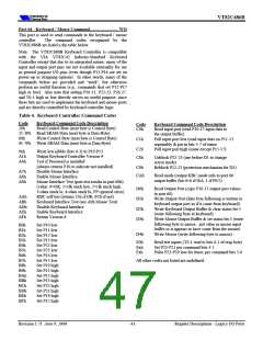
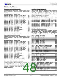
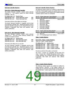
VT82C686B
Super-I/O Configuration Index / Data Registers
Super-I/O Configuration Registers
Super-I/O configuration registers are accessed by performing
I/O operations to / from an index / data pair of registers in
system I/O space at port addresses 3F0h and 3F1h. The
configuration registers accessed using this mechanism are used
to configure the Super-I/O registers (parallel port, serial ports,
IR port, and floppy controller).
These registers are accessed via the port 3F0 / 3F1 index / data
register pair using the indicated index values below
Index E0 – Super-I/O Device ID (3Ch) ............................ RO
........................................ default = 3Ch
7-0 Super-I/O ID
Index E1 – Super-I/O Device Revision (00h)................... RO
.........................default = 0
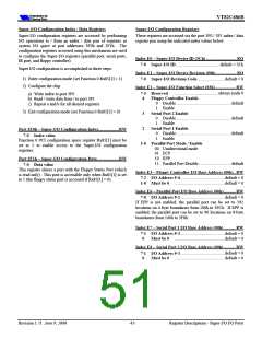
Super I/O configuration is accomplished in three steps:
1) Enter configuration mode (set Function 0 Rx85[1] = 1)
2) Configure the chip
7-0 Super-I/O Revision Code
Index E2 – Super-I/O Function Select (03h)................... RW
........................................always reads 0
7-5 Reserved
a) Write index to port 3F0
4
3
2
Floppy Controller Enable
b) Read / write data from / to port 3F1
c) Repeat a and b for all desired registers
0
Disable................................................... default
1
Enable
3) Exit configuration mode (set Function 0 Rx85[1] = 0)
Serial Port 2 Enable
0
Disable................................................... default
1
Enable
Serial Port 1 Enable
Port 3F0h – Super-I/O Configuration Index...................RW
0
Disable................................................... default
7-0 Index value
1
Enable
Function 0 PCI configuration space register Rx85[1] must be
set to 1 to enable access to the Super-I/O configuration
registers.
1-0 Parallel Port Mode / Enable
00 Unidirectional mode
01 ECP
10 EPP
Port 3F1h – Super-I/O Configuration Data....................RW
11 Parallel Port Disable.............................. default
7-0 Data value
This register shares a port with the Floppy Status Port (which
is read only). This port is accessible only when Rx85[1] is set
to 1 (the floppy status port is accessed if Rx85[1] = 0).
Index E3 – Floppy Controller I/O Base Address (00h).. RW
.........................................default = 0
7-2 I/O Address 9-4
..............................................default = 0
1-0 Must be 0
Index E6 – Parallel Port I/O Base Address (00h)........... RW
.........................................default = 0
7-0 I/O Address 9-2
If EPP is not enabled, the parallel port can be set to 192
locations on 4-byte boundaries from 100h to 3FCh. If EPP is
enabled, the parallel port can be set to 96 locations on 8-byte
boundaries from 100h to 3F8h.
Index E7 – Serial Port 1 I/O Base Address (00h)........... RW
.........................................default = 0
7-1 I/O Address 9-3
..............................................default = 0
0
Must be 0
Index E8 – Serial Port 2 I/O Base Address (00h)........... RW
.........................................default = 0
7-1 I/O Address 9-3
..............................................default = 0
0
Must be 0
Revision 1.71 June 9, 2000
-45-
Register Descriptions - Super-I/O I/O Ports

 ETC [ ETC ]