VT82C686B
Keyboard Controller Registers
Port 64 - Keyboard / Mouse Status .................................. RO
7
Parity Error
The keyboard controller handles the keyboard and mouse
interfaces. Two ports are used: port 60 and port 64. Reads
from port 64 return a status byte. Writes to port 64h are
command codes (see command code list following the register
descriptions). Input and output data is transferred via port 60.
0
No parity error (odd parity received)..... default
1
Even parity occurred on last byte received
from keyboard / mouse
6
5
4
3
2
1
0
General Receive / Transmit Timeout
0
No error ................................................. default
A “Control” register is also available. It is accessable by
writing commands 20h / 60h to the command port (port 64h);
The control byte is written by first sending 60h to the
1
Error
Mouse Output Buffer Full
0
Mouse output buffer empty.................... default
command port, then sending the control byte value.
The
1
Mouse output buffer holds mouse data
control register may be read by sending a command of 20h to
port 64h, waiting for “Output Buffer Full” status = 1, then
reading the control byte value from port 60h.
Keylock Status
0
Locked
1
Free
Traditional (non-integrated) keyboard controllers have an
“Input Port” and an “Output Port” with specific pins dedicated
to certain functions and other pins available for general
purpose I/O. Specific commands are provided to set these pins
high and low. All outputs are “open-collector” so to allow
input on one of these pins, the output value for that pin would
be set high (non-driving) and the desired input value read on
the input port. These ports are defined as follows:
Command / Data
0
Last write was data write ....................... default
1
Last write was command write
System Flag
0
Power-On Default.................................. default
1
Self Test Successful
Input Buffer Full
0
Input Buffer Empty................................ default
1
Input Buffer Full
Bit Input Port
Lo Code Hi Code
Keyboard Output Buffer Full
0
1
2
3
4
5
6
7
P10 - Keyboard Data In
B0
B1
B2
B3
B6
B7
–
B8
B9
BA
BB
BE
BF
–
0
Keyboard Output Buffer Empty............. default
P11 - Mouse Data In
P12 - Turbo Pin (PS/2 mode only)
P13 - user-defined
P14 - user-defined
P15 - user-defined
1
Keyboard Output Buffer Full
KBC Control Register..........(R/W via Commands 20h/60h)
........................................always reads 0
PC Compatibility
7
6
Reserved
P16 - user-defined
P17 - undefined
0
Disable scan conversion
–
–
1
Convert scan codes to PC format; convert 2-
byte break sequences to 1-byte PC-compatible
break codes............................................ default
Bit Output Port
Lo Code Hi Code
0
1
2
3
4
5
6
7
P20 - SYSRST (1=execute reset)
P21 - GATEA20 (1=A20 enabled)
P22 - Mouse Data Out
P23 - Mouse Clock Out
P24 - Keyboard OBF Interrupt (IRQ1) –
P25 - Mouse OBF Interrupt (IRQ 12)
P26 - Keyboard Clock Out
P27 - Keyboard Data Out
–
–
B4
B5
–
–
BC
BD
–
–
–
–
5
4
Mouse Disable
0
Enable Mouse Interface ......................... default
1
Disable Mouse Interface
Keyboard Disable
–
–
–
0
Enable Keyboard Interface .................... default
1
Disable Keyboard Interface
........................................always reads 0
................................................default=0
3
2
Reserved
System Flag
This bit may be read back as status register bit-2
Bit Test Port
Lo Code Hi Code
0
T0 - Keyboard Clock In
–
–
1
T1 - Mouse Clock In
–
–
1
Mouse Interrupt Enable
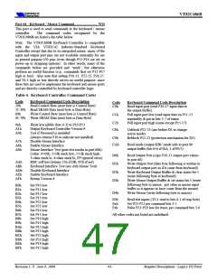
Note: Command code C0h transfers input port data to the
output buffer. Command code D0h copies output port values
to the output buffer. Command code E0h transfers test input
port data to the output buffer.
0
1
Disable mouse interrupts ....................... default
Generate interrupt on IRQ12 when mouse data
comes in output bufer
0
Keyboard Interrupt Enable
0
1
Disable Keyboard Interrupts.................. default
Generate interrupt on IRQ1 when output buffer
has been written.
Port 60 - Keyboard Controller Input Buffer ................. WO
Only write to port 60h if port 64h bit-1 = 0 (1=full).
Port 60 - Keyboard Controller Output Buffer ................RO
Only read from port 60h if port 64h bit-0 = 1 (0=empty).
Revision 1.71 June 9, 2000
-40-
Register Descriptions - Legacy I/O Ports

 ETC [ ETC ]