VT82C686B
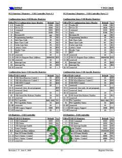
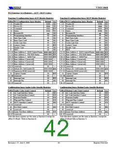
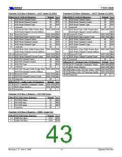
PCI Function 5 & 6 Registers – AC97 / MC97 Codecs
Function 5 Configuration Space AC97 Header Registers
Function 6 Configuration Space MC97 Header Registers
Offset PCI Configuration Space Header
1-0 Vendor ID
3-2 Device ID
5-4 Command
7-6 Status
Default Acc
Offset PCI Configuration Space Header
1-0 Vendor ID
3-2 Device ID
5-4 Command
7-6 Status
Default Acc
RO
RO
RW
WC
RO
RO
RO
RO
RO
RW
RO
RO
RO
RO
RW
WC
RO
RO
RO
RO
RO
RW
RO
RO
1106
3058
0000
0210
nn
00
01
04
00
1106
3068
0000
0200
nn
00
80
07
00
8
9
Revision ID
8
9
Revision ID
Programming Interface
Sub Class Code
Base Class Code
Cache Line Size
Latency Timer
Header Type
Programming Interface
Sub Class Code
Base Class Code
Cache Line Size
Latency Timer
Header Type
A
B
C
D
E
F
A
B
C
D
E
F
00
00
00
00
00
00
BIST
BIST
13-10 Base Address 0 - SGD Control/Status
17-14 Base Address 1 - FM NMI Status
1B-18 Base Address 2 - MIDI Port
1F-1C Base Address 3 (reserved)
23-20 Base Address 4 (reserved)
27-24 Base Address 5 (reserved)
28-29 -reserved-
13-10 Base Address 0 - SGD Control/Status
17-14 Base Address 1 - FM NMI Status
1B-18 Base Address 2 - MIDI Port
1F-1C Base Address 3 (reserved)
23-20 Base Address 4 (reserved)
27-24 Base Address 5 (reserved)
28-29 -reserved-
0000 0001 RW
0000 0001 RW
0000 0001 RW
0000 0001 RW
0000 0000
RW
0000 0000 —
0000 0000 —
0000 0000 —
0000 0000
RW
0000 0000 —
0000 0000 —
0000 0000 —
00
—
00
—
2F-2C Subsys ID / SubVendor ID
33-30 Expansion ROM (reserved)
34 Capture Pointer
35-3B -reserved-
3C Interrupt Line
0000 0000
0000 0000 —
2F-2C Subsys ID / SubVendor ID
33-30 Expansion ROM (reserved)
34 Capture Pointer
35-3B -reserved-
3C Interrupt Line
0000 0000
0000 0000 —
RW
RW
00
00
00
03
00
00
00
00
03
00
RW
—
RW
RO
—
RW
—
RW
RO
—
3D Interrupt Pin
3E-3F -reserved-
3D Interrupt Pin
3E-3F -reserved-
Configuration Space Audio Codec-Specific Registers
Configuration Space Modem Codec-Specific Registers
Offset Audio Codec Link Control
40 AC-Link Interface Status
41 AC-Link Interface Control
42 Function Enable
43 Plug and Play Control
44 MC97 Interface Control
45-47 -reserved-
Default Acc
Offset Modem Codec Link Control
40 AC-Link Interface Status
41 AC-Link Interface Control
42 Function Enable
43 Plug and Play Control
44 MC97 Interface Control
45-47 -reserved-
Default Acc
00
00
RO
RW
RW
RW
RO
—
RO
RW
RW
RW
RW
—
00
00
00
00
1C
00
1C
00
00
00
48 FM NMI Control
49 -reserved-
00
00
48 FM NMI Control
49 -reserved-
00
00
RO
—
RO
—
4B-4A Game Port Base Address
4C-FF -reserved-
0000
00
RW
—
4B-4A Game Port Base Address
4C-FF -reserved-
0000
00
RO
—
Note that these registers are the same as function 6 except for
offset 44 (Read / Write in function 6)
Note that these registers are the same as function 5 except for
offset 44 (Read Only in function 5)
Revision 1.71 June 9, 2000
-36-
Register Overview

 ETC [ ETC ]