VT82C686B
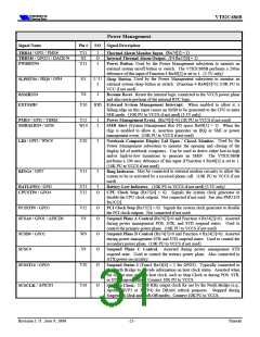
Power Management
Signal Name
Pin #
I/O Signal Description
/ GPI5 / PME#
T11
N2
Y11
I
O
I
(Rx74[1] = 1)
THRM
Thermal Alarm Monitor Input.
/ GPO21 / DACK7#
(F4 Rx57[0] = 1)
THRM#
Internal Thermal Alarm Output.
Used by the Power Management subsystem to monitor an
Power Button.
PWRBTN#
external system on/off button or switch. The VT82C686B performs a 200us
debounce of this input if Function 4 Rx40[5] is set to 1. (3.3V only)
/ IRQ6 / GPI4
G1
I / I /
I
Used by the Power Management subsystem to monitor an
Sleep Button.
external system sleep button or switch. (Function 4 Rx40[6]=1) (10K PU to
VCC if not used)
SLPBTN#
V6
I
Resets the internal logic connected to the VCCS power plane
and also resets portions of the internal RTC logic.
When enabled to allow it, a
External System Management Interrupt.
RSMRST#
EXTSMI#
Resume Reset.
Y10
IOD
falling edge on this input causes an SMI# to be generated to the CPU to enter
SMI mode. (10K PU to VCCS if not used) (3.3V only)
/ GPI5 / THRM
T11
W10
I
I
(Rx74[1]=0) (1K PU to VCCS if not used)
Power Management Event.
(System Management Bus I/O space Rx08[3] = 1). When the
SMB Alert
PME#
/ GPI6
SMBALRT#
chip is enabled to allow it, assertion generates an IRQ or SMI or power
management event. (10K PU to VCCS if not used)
/ GPI3 / WSC#
U10
I
Used by the
Notebook Computer Display Lid Open / Closed Monitor.
LID
Power Management subsystem to monitor the opening and closing of the
display lid of notebook computers. Can be used to detect either low-to-high
and/or high-to-low transitions to generate an SMI#. The VT82C686B
performs a 200 usec debounce of this input if Function 4 Rx40[5] is set to 1.
(10K PU to VCCS if not used)
/ GPI7
V11
I
May be connected to external modem circuitry to allow the
Ring Indicator.
RING#
system to be re-activated by a received phone call. (10K PU to VCCS if not
used)
/ GPI2
/ GPO4
U11
Y12
I
O
(10K PU to VCCS if not used) (3.3V only)
(Rx75[4] = 0). Signals the system clock generator to
BATLOW#
CPUSTP#
Battery Low Indicator.
CPU Clock Stop
disable the CPU clock outputs. Not connected if not used. See also PMU I/O
Rx2C[3].
/ GPO5
V12
V9
O
O
(Rx75[5] = 0). Signals the system clock generator to disable
the PCI clock outputs. Not connected if not used.
PCISTP#
PCI Clock Stop
/ GPO1 / APICD0
/ GPO2
(Rx74[7]=0 and Function 4 Rx54[2]=0). Asserted
SUSA#
SUSB#
SUSC#
SUSST1#
Suspend Plane A Control
during power management POS, STR, and STD suspend states. Used to
control the primary power plane. (10K PU to VCCS if not used)
(Rx74[7]=0 and Function 4 Rx54[3]=0). Asserted
Suspend Plane B Control
during power management STR and STD suspend states. Used to control the
secondary power plane. (10K PU to VCCS if not used)
W9
Y9
O
O
O
Asserted during power management STD
Suspend Plane C Control.
suspend state. Used to control the tertiary power plane. Also connected to
ATX power-on circuitry.
(Func4 Rx54[4] = 1 for GPO3). Typically connected to
Suspend Status 1
/ GPO3
V10
the North Bridge to provide information on host clock status. Asserted when
the system may stop the host clock, such as Stop Clock or during POS, STR,
or STD suspend states. Connect 10K PU to VCCS.
/ APICD1
T10
O
32.768 KHz output clock for use by the North Bridge (e.g.,
Suspend Clock.
SUSCLK
Apollo MVP3 or MVP4) for DRAM refresh purposes. Stopped during
Suspend-to-Disk and Soft-Off modes. Connect 10K PU to VCCS.
Revision 1.71 June 9, 2000
-25-
Pinouts

 ETC [ ETC ]