VT82C686B
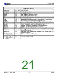
Parallel Port Interface
Signal Name
Pin #
I/O
Signal Description
/ DIR#
C15
D16
C16
IO / O
IO / -
IO / O
Initialize printer. Output in standard mode, I/O in ECP/EPP mode.
Initialize.
PINIT#
/ nc
Output used to strobe data into the printer. I/O in ECP/EPP mode.
STROBE#
AUTOFD#
Strobe.
/ DRVEN0
Output used to cause the printer to automatically feed one line after
Auto Feed.
each line is printed. I/O pin in ECP/EPP mode.
/ STEP#
/ WGATE#
/ DS1#
E15
E13
B13
IO / O
I / O
I / O
Output used to select the printer. I/O pin in ECP/EPP mode.
Status output from the printer. High indicates that it is powered on.
SLCTIN#
SLCT
ACK#
Select In.
Select.
Status output from the printer. Low indicates that it has received
Acknowledge.
the data and is ready to accept new data
/ HDSEL#
A15
I / O
Status output from the printer. Low indicates an error condition in the
ERROR#
Error.
printer.
/ MTR1#
/ WDATA#
C13
D13
A13,
E14,
D14,
C14,
B14,
A14,
D15,
B15
I / O
I / O
Status output from the printer. High indicates not ready to accept data.
BUSY
PE
Busy.
Status output from the printer. High indicates that it is out of paper.
Paper End.
/ nc,
/ nc,
/ nc,
/ DSKCHG#,
/ RDATA#,
/ WRTPRT#,
/ TRK00#,
IO / -
IO / -
IO / -
IO / I
IO / I
IO / I
IO / I
IO / I
PD7
PD6
PD5
PD4
PD3
PD2
PD1
PD0
Parallel Port Data.
/ INDEX#
As shown by the alternate functions above, in mobile applications the parallel port pins can optionally be selected to function as a
floppy disk interface for attachment of an external floppy drive using the parallel port connector (see Super I/O Configuration
Index F6[5]).
Revision 1.71 June 9, 2000
-16-
Pinouts

 ETC [ ETC ]